No. 5) |
TRAVELLIN BUCKET DREDGER, or CONVEYOR
Special Features. Three distinct movements, i.e. travelling, raising and lowering of Bucket Arm, and operation of Bucket Chain |
Fig. 1General view of the Dredger, showing Hornby Side-tipping Wagons in position for loading. 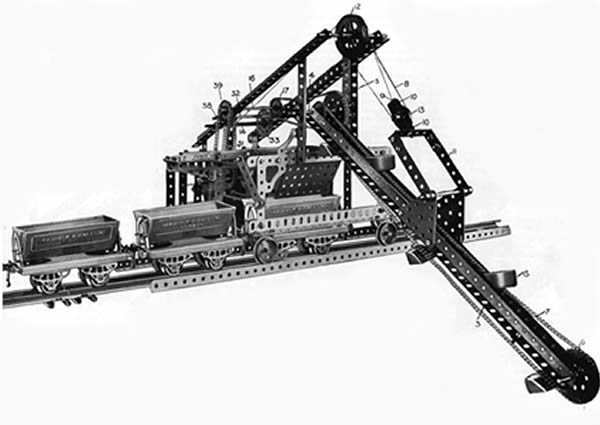
A fine working model that can be used in conjunction with Hornby Trains. |
Pag.1.
In the case of the dredger reproduced in Meccano, a railway line runs through the centre of the machine, and the material removed by the buckets is deposited via a chute into a railway truck placed directly underneath. As each truck is loaded, it is moved on and replaced by another until a complete train is formed, when the material may be removed to any convenient point. From this it will be seen that the model is an ideal one for use in conjunction with Hornby model railways, and for this reason it will appeal to a very large number of boys.
The Meccano Model
 Fig.2. Inner side of Gear Box, looking toward the driving platform.
In Fig. 1 three Hornby Side-tipping Wagons are shown in use in con
junction with the model, one wagón being in position under the chute to
receive its load. In practice the rails that carry the Flanged Wheels on which
the dredger runs are laid along the edge of the dock wall or revetment, etc., a
standard railway line being laid between these guide rails. The six Flanged
Wheels of the Meccano model run on rails formed from Angle
Girders, but if desired Hornby Rails may be used for the purpose.
If the chute is lined with cardboard or tin píate the model can be made to
(2) starting and stopping the movement of the Buckets up and down the Bucket Arm : and (3) causing the entire machine to move to and fro on its track. These movements can be obtained separately or simultaneously, and the reverse in each case is effected by moving the Motor control switch.
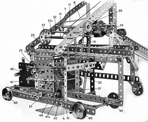
Construction of the Framework
The framework of the Dredger is shown in Fig. 3. In the centre is seen the chute, which receives the material removed by the Buckets and allows it to fall into the wagón that has been shunted underneath. It consists of a
Pag. 2
3 1/2" by 2 1/2" Flanged Píate bolted to a pair of 2 1/2" Triangular Piales, which are carried on two 3 1/2" by 1/2" Double Angle Strips as shown.
The 12 1/2" Angle Girders 51 are bolted near their upper ends to two 5 1/2" Angle Girders and at their lower ends to two 1" by 1" Angle Brackets 52. These Angle Brackets are bolted to a 5 1/2" Strip 53 which in turn is fastened to the 3 1/2" Flanged Píate 54. In Fig. 3 only a small portion of the 5 1/2" Strip can be seen, part of it having been removed in order to show the other details of the framework more clearly. Actually the end of the 5 1/2" Strip is fastened to the top of a vertical Double Angle Strip 55 as shown in Fie;. 5. The 5 1/2" Strip 56 (only a portion of which can be seen in Fig. 3) is also bolted to the Strip 53.
The Bucket Arm
The bucket arm, which is shown clearly in Fig. 1, is built up from two 18 1/2" Angle Girders 3 joined by 2" Strips and braced near the centre by diagonally-disposed 3" Strips. It is pivoted on a Rod 4, and a 1" Sprocket Wheel is placed on this Rod between the Angle Girders 3. A 2" Sprocket Wheel 6 is carried on a 2" Rod journalled in the lowest holes of the arm, and a length of Sprocket Chain 7 is led over these wheels and five or more Dredger Buckets are attached to the Chain at equal intervals. A 2" Sprocket Wheel is also fastened on the Rod 4 and is driven from a 1" Sprocket 17 on the Rod 16 by means of a Sprocket Chain.
To the centres of the 18 1/2" Girders 3 two 2 1/2" Triangular Piales are atlached by means of Angle Erackels, and a yoke consisting of two 3 1/2" Strips 11 and one 2 1/2" by 1" Double Angle Strip is atlached pivotally to these Piales by means of a 3 1/2" Rod and four Collars. A supporl for the 1" Pulley Wheel 13 is made from two Cranked Benl Slrips held logelher by a 1" Rod and two Collars. In the end holes of the 12 1/2" Girders 51 is journalled a 4 1/2" Axle Rod carrying two 2" Pulley Wheels 12, free on the Rod.
The hoisting cord is faslened to one of the holes of the Cranked Bent Strips 10, and passed over one of the 2" Pulleys 12 and round the 1" Pulley 13. It is then led over ihe second 2" Pulley Wheel 12 and wound on the Axle Rod 14.
Gear Box and Clutch Mechanisms
Fig.4. Inner side of Gear Box, from driving plataform end. 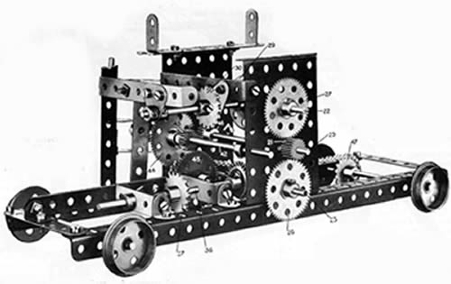
The arrangement of the mechanism. operating levers, etc., should be clear on reference to Figs. 2, 4 and 5. The latler illuslralion is a general view the gear box, showing the operating levers and driving platform (a 2 1/2" by 2 1/2 Fíat Píate) in the foreground. Fig. 2 shows the inner side of the gear box, looking towards the driving platform end, while Fig. 4 is a view of the same side laken from ihe plalform end.
The drive from the armature spindle of ihe Electric Motor is transmilled to the various portions of the model as follows. The 1/2" Pinion 48 on the spindle (Fig. 5) meshes wilh a 57-teeth Gear Wheel secured to a Rod journalled in the side piales of the Motor. This Rod carries a further 5 1/2" Pinion situated inside ihe Motor. A 2 1/2" Axle Rod journalled in ihe end holes of the Motor frame carries a second 57-teelh Gear Wheel engaging ihe leelh of this 1/2" Pinion. It is provided also with a 1/2" Pinion thal meshes with a 50-teelh Gear Wheel on ihe Rod 20 (see Figs. 2 and 4). In Figs. 2 and 4 the Electric Molor has been removed, logelher wilh ihe mechanism mounled on il and the 50-teelh Gear Wheel on the Rod 20, in order to show the remaining gears more clearly.
The hoisting movemenl of ihe buckel arm is effecled from ihe Rod 22. This Rod carries a 57-leeth Gear Wheel 27, a 1/2" Pinion 28, and ihe clulch mechanism. This mechanism, which is idenlical on all three sliding Rods 22, 23 and 42, consists of a Double Bracket retained in posilion on ihe end of ihe Rod by two Collars. Washers being placed between the inner Collar and the Flanged Plate. The operating lever consists of a 3 1/2" Slrip wilh a . 4.
Threaded Pin altached
It is pivoted to the Double Brackel by means of
a boíl and two nuts (see Standard Mechanism No. 262) and at its other end to a 1" by 1" Angle Bracket bolted to the side of the gear box. By moving the Threaded Pins ihe Rods 22, 23 and 42 can be slid in iheir bearings, and different sets of gears may thereby be brought into operation.
Thus, either of ihe Gear Wheels 26, 27 (Figs. 2 and 4) can be brought into gear with the 1/2" Pinion 21 on the Rod 20 by means of the Clutch levers 24 and 25. The 1/2" Pinion 28 on the Rod 22 is in constant engagemenl with a 1 1/2" Contrate Wheel 29 and the Rod to which the Céntrale is secured also bears al 1" Sprocket Wheel 30 (Fig. 5), which is coupled to a similar Sprocket Wheel on the Rod 32 by a Chain 31. The Rod 32 carries a 1/2" Pinion 33a that, by means of the 57-teeth Gear Wheel 33, rotates the winding spindle 14, on which is wound the Cord 8 that opérates the bucket arm. It will be seen that if the clutch lever 24 is pushed inward, ihe above-
Pag. 3
mentioned train of gears comes into operation, so raising or lowering the bucket arm. Fig. 5. Gral. view of the driving mechanism, showing,Electric Motor in position.
------------------------------------------------------------------------------------------------------------------------------------------------------------------------------------------ List of Parts required for building the Travelling Bucket Dredger.
Pag.4. |