(No.2
)
SPECIAL INSTRUCTION LEAFLETS FOR MECCANO SUPER MODELS
An L Outfit Model
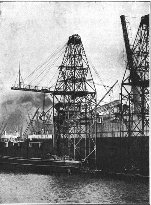
Giant Ship Coaler at work Coaling a Liner.
The
Meccano High-Speed Ship Coaler
As soon as the steamship had passed the experimental stage and had become a practical proposition, it was natural that engineers should begin to visualise the immense possibilities that were opened up. Short voyages had been carried out with perfect success, and it was realised that the next step should be the crossing of the Atlantic. Among the prominent engineers of that day who turned their attention to this problem was I. K. Brunei. Throughout his career his brilliant mind worked on big lines, and the steamship conquest of the Atlantic must have appealed to him very strongly. We are told that in 1835, at a meeting of the Directors of the Great Western Railway, one of the party remarked upon what he regarded as the enormous length of the proposed railway from London to Bristol. Brunei immediately exclaimed: "Why not make it longer, and have a steamboat to go from Bristol to New York, and call it the 'Great Western"'' Most of those present treated the suggestion as a joke, but Brunei was in grim earnest, and in due course the construction of the "Great Western" was commenced.
The crossing of the Atlantic by a steam-propelled vessel obviously-involved a very large consumption of coal, and a heated controversy arose as to whether it was possible for any steamship to carry a sufficient supply of coal to enable her to cover the distance. Brunei was quite satisfied in regard to this matter, but his views were strongly opposed by one Dr. Dionysius Lardner, who at that time was a prominent figure in the scientific world. At a meeting of the British Association held at Bristol in 1836, Lardner expressed himself very emphatically regarding the impossibility of a direct crossing of the Atlantic. In the course of his lecture he said :—
Page.1
"
Let them take a vessel of 1,600 tons, provided with 400 horse-power engines.
They must take 2j tons for each horse-power, the vessel must have 1,348
tons of coal, and to that add 400 tons, and the vessel must carry a burden
of 1,748 tons. He thought it would be a waste of time, under all the circumstances,
to say much more to convince them of the inexpediency of attempting a
direct voyage to New York for in this case 2,080 miles was the longest
run a steamer could encounter : at the end of that distance she would
require a relay of coals."Not content with this, Dr. Lardner painted
a melancholy picture of the objections to long voyages that would result
from the choking of smoke flues and the incrustation of boilers!
Dr. Lardner's views made a considerable impression at the time, but 109
Brunei never hesitated. The "Great Western " was finished and
launched, and made many crossings of the Atlantic Ocean with perfect success.
For a long period the coaling of steamships was carried out entirely by
land labour, and even to-day this is the case in many Eastern ports. Coaling
by hand cannot be otherwise than a dirty operation, causing intense discomfort
to all on board. The late Sir Frederick Treves, in his interesting book
"The Other Side of the Lantern" gives a graphic description
of the miseries of coaling at Port Said. "Clouds of coal-dust envelop
the poor vessel," he says, " and penetrate into every part of
it. The deck becomes an ashdrift. Whatever the hand finds to touch, it
12 finds to be black. Coal-dust becomes the breath of the nostrils, coal-dust
settles upon the face, powders the neck, and creeps among the hair.
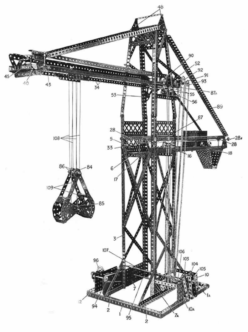
Fig. 1 Ship Coaler
Moreover, in no part of the ship is there any escape from the husky din
which accompanies the ritual of coaling.
On this occasion the coaling took place at night from great coal carrying
rafts containing gangs of hundreds of coolies. Each raft carries high
aloft cressets or iron baskets blazing with fire. "The rafts are
made fast to the great vessel, planks are run up to the coal bunkers,
and then there begins an un ceasing procession of gaunt folk carrying
yellow baskets full of coal up one plank and return-ing with them empty
along another.
As they pass up and down, their rags dance in the wind, clouds of coal
dust and smoke circle round them, while the light from the cressets flashes
fitfully upon the file, making their sweating limbs glow as with a fervent
heat. The stream of basket carriers might be coming out from the crater
of a volcano, and it is a matter of wonder that they are neither charred
nor smothered. .....
"Hour after hour the dry tramp of feet along the plank continues,
hour after hour the same hoarse dirge is screamed forth from a hundred
creakin
Page.2
throats, hour after hour the spades are at work and the baskets come and
go. Then the scuffle of feet ceases, the scrape of the shovels dies away,
the fire in the cressets flutters out, the barges are empty, and to the
same weird chant they glide away and are lost in the gloom."
Coaling by Machinery.
Coaling by hand on these lines is only possible in parts of the world
where ample and cheap native labour is available. Else¬where machinery
must be called into play to carry out operations at a sufficient speed,
and yet economically. The method employed for transferring the coal from
the quayside to the ship's bunkers varies considerably in different ports,
according to local conditions and circumstances. The coaling facilities
of the larger ports are naturally on a more elaborate and more interesting
scale than those at the smaller ports. At several of the larger ports,
for instance, there are whole fleets of floating coaling machines operated
by grabs in conjunction with belt conveyor, and also by bucket elevators
and chutes. These machines correspond very closely in their working principles
to the Meccano model shortly to be described.
The grab machines do not themselves carry any coal, but are moored alongside
the vessel to be coaled, and barges containing the coal are brought alongside
the grab machines. The grab is lowered into the barge, from which it takes
up in its great steel jaws a mouthful of coal weighing something over
a ton. This coal is raised to whatever height may be required and is then
released on to
a travelling belt conveyor, by which it is carried across the deck of
the vessel to the hatchways. In the Meccano model, the automatic discharging
truck corresponds to the belt conveyor.
While the coal is on its journey along the conveyor the grab descends
again and takes up another load, and so the process goes on, the loading
proceeding at the rate of over 100 tons per hour. As soon as one barge
is emptied, another one takes its place, so that the loading continues
without interruption until the necessary amount of coal has been taken
on board.
The photograph on page 1 shows the giant grab elevator "Pensarn,"
which belongs to Rea Limited, engaged in coaling a liner in the Liverpool
docks. In order to make it possible to coal ships in any part of the dock
system, the entire structure is built on a flat barge or pontoon, which
may be brought close up to the side of the vessel to
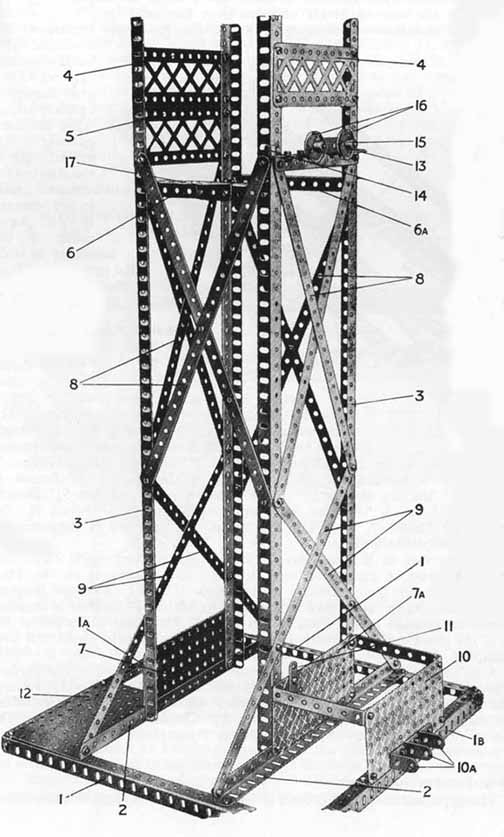
Fig. 2
Lower Portion
of Tower with Base and frame of Gear-Box in position
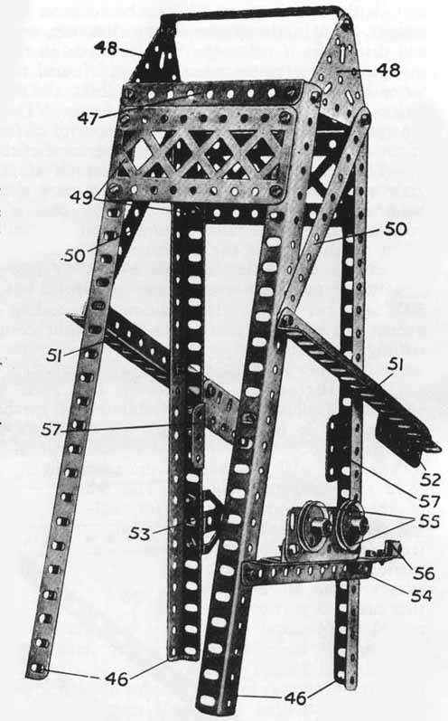
Fig.3 Upper Portin of Tower
Page. 3
be
coaled. The grab, which is suspended from a trolley in the same way
as that in the Meccano model, can be seen on the left of the photograph.
A hopper, seen in the centre of the structure, receives the coal from
the grab and discharges it on to the belt conveyor on the right. The
grab bucket of this particular elevator raises 22 cwt. of coal to a
height of 60 ft. above the water line. When working at these limits
the machine is capable of delivering into a steamer 120 tons of coal
per hour. The special barges used in con¬junction with the elevator
have a capacity of from 500 to 1,500 tons. One of these barges can be
seen in the foreground of the photograph.
The machines operated by bucket elevators and chutes differ from the
grab machines in that they themselves carry the coal. They are capable
of holding from 1,000 to 1,100 tons. The coal is made to fall in regulated
quantities through a false bottom on to a travelling chain of buckets,
which lift it to the top of the machine and discharge it down chutes
directed either over the decks into hatchways, or into side ports. By
means of elevator machines coaling can be carried out at the rate of
some 300 tons per hour. In addition, the coaling can be delivered overall
to a height of more than 50 ft., thus ensuring the speedy coaling of
a large liner without any necessity for the vessel to move from her
loading or discharging berth.
The High-speed Ship Coaler has been designed specially to illustrate
the possibilities of mechanical coaling. It is one of the most interesting
of all Meccano models, and if carefully constructed it operates with
wonderful precision and in a most realistic manner. The whole of the
movements necessary for coaling a miniature ship are controlled from
a central gear-box, and are carried out with perfect ac curacy. The
model is one that makes a particular appeal to Meccano enthusiasts,
because, in addition to the enjoyment
of building it, it affords endless fun when com pleted. More over, a
considerable amount of dexterity is re quired for its
successful manipulation. There are so many movements that the operator
has to use his intelligence all the time, and must be quick with his
fingers in order to carry out the various stages without a hitch. In
other words, it is just as exciting to operate as it is to build.
At first sight the Meccano Ship Coaler may seem to differ considerably
from the elevators used in actual practice, but a closer inspection
will reveal the fact that the only important variation from the usual
type is the substitution of an automatically-discharging truck for the
more orthodox belt.conveyor. This hasinvolvedthe raising of the grab
runway to agreater height, while the comparative size and strength of
the Angle Girders, etc., used in the Meccano model have made it unnecessary
to build the tower as wide as in the prototype.
The
construction of the model should be commenced by building the main
tower.
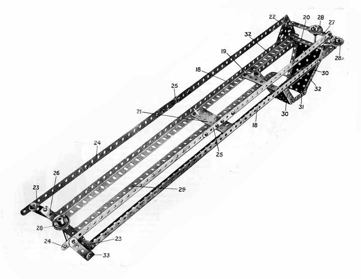
Fig.4 truck runway with Chute
with superstructure, gearing, etc., removed. The base of the tower consists
of four 12 1/2" Angle Girders 1 bolted in the form of a square
and spanned by two similar Girders 2. Four 24 1/2" Angle Girders
3,forming the chief supports of the tower, are braced at the top by
the 5 1/2" Angle Girders 6, 6a and the 5 1/2" Braced Girders
4, 5, whilst their lower ends are joined by two 5 1/2x2 1/2" Flat
Plates, 7, 7a. The rigidity of the structure is increased by 12 ½
crossed Strips 8, 9.
The framework of the gear-box is formed by erecting a 5 1/2x2 1/2"
Flat Plate 10 edgewise on one of the base Girders 1 and joining it to
the Plate 7a by means of two 3 1/2 x 1/2" Double Angle Strips.
Three 1x1" Angle Brackets l0a are secured to the outer side of
the Plate 10, and a 1 1/2" Strip 11 is attached in a vertical position
to the Plate 7a. A 5 1/2x3 1/2" Flat Plate 12, bolted to the base
in the position shown forms the bed to which an Electric Motor will
later be attached.
A 5 1/2" Angle Girder 13 bolted near the upper ends of two of the
Girders 3, above the gear-box, carries a Crank 14, and a 2" Angle
Girder 15, secured to the Girder 13, carries two 1" loose Pulley
Wheels 16, which are mounted on Threaded Pins and kept in position by
Collars and set screws. The addition of a Trunnion 17 to the Girder
6 completes the construction of the main tower unit.
Upper Portion of Tower.
The upper tower (Fig. 3) is built of four 12 1/2" Angle Girders
46 surmounted
Page.4
by two 4
½” Angle Girders 47 and two 2 ½” Triangular
Plates 48 joined by a 4 1/2x1/2” Double Angle Strip. The wider sides
of the tower are strengthened by 4 ½” Braced Girders 49,
and the narrow sides by two 5 ½” Strips 50. To the ends of
these Strips 50 are bolted the 7 ½” Angle Girders 51, the
projecting ends of which slope downward and carry 2 ½” Flat
Girders 52. Below the Girders 51, two 1 ½” Angle Girders
57 are attached to the uprights 46 as shown, and further down, on one
side only, is a Trunnion 53.
The 5 ½” Angle Girder 54 carries a 3” Angle Girder
and a 3” Flat Girder, to which the 1 ” loose Pulleys 55 are
attached by Threaded Pins in the same way as the Pulleys 16 (Fig. 2).
A Crank 56 is bolted as shown (Fig. 3) to the short projecting end of
the Girder 54.
The Truck Runway
The construction
of the truck runway, chute, etc., will be followed from Fig. 4. Two 24
½” Angle Girders 18, separated by 3 ½” Strips
19, 20 and a pair
A 1” loose Pulley 28a is free to rotate about a Threaded Pin secured
in a Trunnion, which in turn is bolted to one of the Triangular Plates
22. A Collar with grub-screw keeps the Pulley in position. A 11/2x1/2”
Double Angle Strip 33 is bolted to the end of one of the Strips 24.
The guide rail 29 consists of two 12 1/2” Strips, one end of each
Strip being clamped between two Flat Girders 21; this rail also passes
between two 3 1/2” Strips 19, and its end is curved downward to
overhang the chute. The latter consists of two Sector Plates 30 joined
by 2” Strips 31 and bolted to 51/2” Angle Girders 32 on the
underside of the rails 18.
The Flanged Wheels of the automatically-discharging truck run on the edges
of the outer vertical sides of the Angle Girders 18.
The Grab Runway
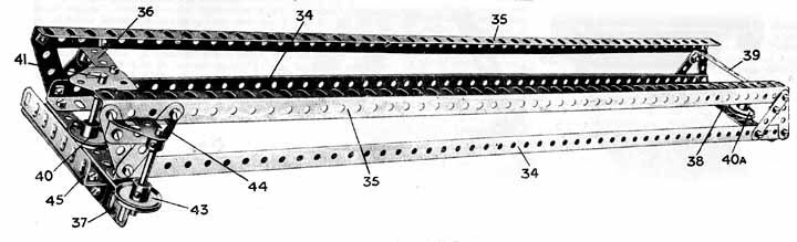
Fig. 5 shows the runway traversed by the trolley from which the grab is
suspended. The rails 34 and the strengthening members 35 consist of 24
1/2”
of 3 ½” Flat Girders 21, are the rails on which the truck
(Fig. 6) runs. At the outer ends of the rails are the 2 1” Triangular
Plates 22, and at the inner ends are the 2 ½” Strips 23.
The latter are joined to the Plates 22 by the Strips 24, which consist
of 12 ½” Strips connected end to end by overlapping 3”
Strips 25.
Two 3 1” Strips 26, 27 are attached respectively to the Strips 23
and the Triangular Plates 22 by means of Angle Brackets, and short Rods
journalled through the middle holes of these Strips carry 1” fast
Pulleys 28, the Rod at the outer end of the runway being also journalled
in the 3A” Strip 20. As will be explained, an additional bearing
for the Rod 28 is provided when the runway is attached to the main tower.
The Strips 26, 27 are used together with Angle Brackets in preference
to 3 1/2x ½” Double Angle Strips, since they permit the Strips
24 to be spaced exactly at the desired distance apart.
Angle Girders, and are joined vertically at each end by a pair of 2”
Strips. These 2” Strips are arranged in such a way that the Girders
35 project 3/4” further from the tower than the rails 34. The rails
are spaced apart by the 41” Angle Girder 37 (the end of which projects
1”) and the 3 1/2” Flat Girder 38, while two 3 1/2x1/2”
Double Angle Strips 36, 39 are bolted between the end 2” Strips.
A 1” loose Pulley Wheel 40a is mounted on a Threaded Pin secured
to the Flat Girder 38, but is prevented from moving vertically by a Collar
and grub-screw. At the outer end of the runway a 1” Pulley Wheel
40 is fixed to a 2” Rod 41 journalled in bearings consisting of
the Girder 37 and a Flat Trunnion bolted to the Double Angle Strip 36.
A second 1” fast Pulley 43 is similarly secured to a 2” Rod
journalled in the projecting end of the Girder 37 and a Trunnion 44 bolted
to one of the pairs of 2” Strips. The 3 1/2” Angle Girder
45 is mounted on a similar Girder bolted to the 41/2” Angle Girder
37.
The flanges of the grab trolley wheels ride on the inner edges of the
horizontal flanges of the Angle Girders 34. For this reason care must
be taken to see that the rails 34 are exactly parallel to one another
before they are finally secured in position.
Page 5
The Truck
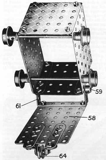 Fig.6
Automaticalli-Discharging Truck
Fig.6
Automaticalli-Discharging Truck
Fig. 6 is
a view of the underside of the automatically - discharging truck, which
runs on the rails 18 (Fig. 4). Two 3 1/2x2 1/2" Flanged Plates joined
by 2 1/2x2 1/2" Flat Plates form the walls of the truck, and the
hinged bottom consists of a 4 1/2x2 1/2" Flat Plate 58. A 3"
Rod 59, journalled in Angle Brackets bolted to one of the end plates,
is retained in position by Collars, and acts as a pivot for a 2 1/2xl"
Double Angle Strip 61 bolted to the Plate 58.
The truck runs on four 3/4" Flanged Wheels secured to 3 ½”
Rods, each wheel being spaced away from the sides of the truck by two
Washers. The ½" loose Pulley Wheel 64 turns freely on a Pivot
Bolt mounted in two Angle Brackets, which are secured to the ends of two
2 1/2" Strips bolted to the" Plate 58. The
Fig. 6. Automatically-Discharging Truck truck wheels run on the upturned
flanges of the rails 18 (Fig. 4).
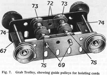
Building
the Grab Trolley.
The grab trolley traverses the rails 34 (Fig. 5) and from it is suspended
the grab.
Two 3 ½" Flat Girders form the sides of the trolley (Fig.
7). They are joined by 1 ½”X ½” Double Angle
Strips 67, and their end holes form journal-bearings for the 3" Axle
Rods carrying the four ¾" Flanged Wheels secured to 3"
Axle Rods. Two 2" Rods 69 journalled in the 3 1/2" Flat Girders
carry two 1 1/2" Strips 72 and three pairs of 1/2" loose Pulley
Wheels 73, 74 and 75, which are spaced apart by fixed Collars. Washers
should be placed between the Pulleys 73 and 75 and the side Girders.
Construction of the Grab.
Each jaw of the grab (Fig. 8) is composed of two 2 1/2" Triangular
Plates pivoted on a 2" Axle Rod 78 and joined by 1 1/2x1/2”
Double Angle Strips 79. Four 2 1/2" Curved Strips (small radius)
are bolted to the Triangular Plates, and to these are attached the 1 1/2"
Strips 80, which are mounted pivotally on 2" Rods 81. Four 3 1/2"
Strips 82 also pivot about Rods 81, and a 21/2" Rod 83 journalled
through their upper ends carries two 1" fast Pulley Wheels 86 and
two 1/2" loose Pulleys 84. The Rods 81 and 83 are held in position
by Collars and grub-screws.
Two 3/4" Flanged Wheels 85 are butted together on the Rod 78 to form
a wide grooved Pulley. The Rod 78 is held in place between the Triangular
Plates by Collars made fast to its ends.
Assembly of the Main Units.
The two portions of the tower are united by bolting the lower ends of
the Angle Girders 46 (Fig. 3) to the tops of the Girders 3 (Fig. 2). The
Angle Girders 18 of the Truck runway (Fig. 4) are then bolted to the Girders
6, 6a, and the outer ends of the runway are supported by two 24 1/2"
Angle Girders 89 (Fig. 1) bolted to the Girders 46 of the upper tower.
The grab runway is mounted pivotally on a 4 1/2" Axle Rod journalled
in the lower holes of the 1 1/2" Angle Girders 57 (Fig. 3) and its
outer end is supported by two ties, each consisting of a 12 1/2"
Angle Girder and a 12 1/2" Strip overlapped nine holes, which connect
it to the top of the tower.
The end of the 2" Rod bearing the 1" Pulley Wheel 28 at the
inner end of the truck runway may now be passed through a hole in the
Trunnion 17 (Fig. 2). A 1/2" loose Pulley Wheel 87 (Fig. 1) is mounted
on a 2" Axle Rod secured in the boss of the Crank 14 (see also Fig.
2) and passes through the 1 1/2" x 1/2" Double Angle Strip 33.
A similar Wheel 87a is supported at the inner end of the grab runway by
a Collar on another 2" Rod that is made fast in the boss of the Crank
56.
The drums on which are wound the cords for operatng the grab are
formed by Meccano Wood Rollers 90, 91 (part No. 106), which are grip¬ped
between Bush Wheels secured to 6 1/2" Axle Rods that arc journalled
in the 2 1/2” Flat Girders 52 (Fig. 3). These Rods are retained
in position by means of Col¬lars and grub-screws, and carry on their
Page 6
ends
the 1" Sprocket Wheels 92, 93. Their other ends pass through the
loops at the ends of two Springs, which are attached to the Trunnion 53
(Fig. 3) and are constantly under tension. The friction thus set up prevents
the weight of the grab from unwinding the cords on the rollers when the
latter are disconnected from the driving mechanism.
A Meccano Electric Motor should next be bolted to the Flat Plate 12 in
the position shown (see Figs. 1 and 9).
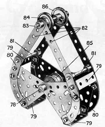
Fig.8 Grab. The sides shoul be filled in with cardboard or additional MECCANO parts, so that the grab can be put to practical use
Transmission and Gearing.
The gear-box and various controls are shown in Fig. 9. The arrangement
of the mechanism is as follows:—A Worm Wheel secured to the armature
spindle of the Electric Motor meshes with a 57-teeth Gear Wheel 96 on
a 2" Rod that is journalled in a Channel Bearing secured to the side
of the motor frame. A 7/8" Bevel Gear, carried on the opposite end
of the 2" Rod, engages with a similar Bevel Gear, from the Rod of
which the drive is led via a 3/4" Sprocket Wheel 94 to a 2"
Sprocket Wheel on the end of the 1 1/2" Axle Rod 95. This Rod 95
passes through the Flat Plates 7a, 10, and is provided with two r Pinion
Wheels 97, 98.
three 6 1/2" Axle Rods 99, 100, 101 are journalled in the side plates
7a and 10 of the gear-box. The first of these carries a 57-teeth Gear
Wheel to mesh with the 1/2" Pinion 97, and two Sprocket Wheels that
engage short Sprocket Chains, to the ends of which are tied lengths of
cord.
The cords thus connected to the inner 1" Sprocket Wheel pass round
the 1" Pulley Wheels 16, 87, 28a, and 28, and are tied to opposite
ends of the truck, while those from the outer Sprocket Wheel are led around
the Pulleys 55, 43, 40, 87a, 40a, and are tied to the grab trolley. When
the Rod 99 revolves, therefore, the truck and the grab trolley are simultaneously
drawn inward or outward. Their positions should be adjusted before securing
so that the grab trolley will come to rest in the tower immediately above
the truck.
The Rod 100 is situated directly above the 11 1/2" Rod 95, and carries
a 57-teeth Gear Wheel to mesh with the 1/2," Pinion 98. It also is
provided with a 1" Sprocket Wheel 102, which is connected by means
of an endless Sprocket Chain to a similar wheel 92 on the spindle of the
Wood Roller 90. A cord wound on this roller passes over one of the 1/2"
loose Pulley Wheels 74 in the grab trolley (Fig. 7), and round the 3/4"
Flanged Wheels 85 of the grab (Fig. 8). It is then carried back and over
the second 1/2" Pulley 74 in the grab trolley and tied to the Angle
Girder 45 at the end of the grab runway (Fig. 5.) The Rod 101 bears a
57-teeth Gear Wheel that can be made to engage with the 1/2" Pinion
97. It is also provided with a 1" Sprocket Wheel, which is connected
by another endless Sprocket Chain to the Sprocket Wheel 93 driving the
roller 91 (Fig. 1). This roller is provided with two cords for raising
and lowering the grab. These cords pass over the 1/2" loose Pulley
Wheels 73, 75 of the grab trolley, under the 1" Pulleys 84 of the
grab,
and back over the second pair of 1/2" Pulley Wheels 73, 75, and are
finally tied to the Angle Girder 45.
The Axle Rods 99, 100, 101 are all slidable in their bearings, and their
movements are controlled by means of the handles 103, 104, 105, consisting
of 3 1/2 " Strips pivotally attached by means of bolts and nuts (S.M.I)
to the 1x1" Angle Brackets lOa (see also Fig. 2). The 3 1/2"
Strips are connected to the sliding Rods by means of Double Brackets,
which are retained in position on the Rods by Collars and pivoted to the
Strips by means of bolts and lock-nuts (S.M. 1A). The Gear Wheels on the
Rods 99, 100, 101 can thus be brought in or out of engagement with the
1/2" Pinion Wheels 97, 98 by operation of their respsctive handles.
The Electric Motor is controlled by a handle 106, consisting of a 2"
Rod secured in the end transverse hole of a Coupling on the extremity
of an 8" Rod 107, which is extended by a Coupling and a 2" Rod.
The latter is attached to the central starting lever of the motor by means
of an End Bearing (part No. 166).
When the handle 105 is pushed inward, the grab closes if the hoisting
mechanism is stationary; if the Electric Motor be reversed, the grab will
open. Operation of the handle 104 causes it to be raised or lowered, but
the handle 105 should be thrown at the same time in order to prevent the
cord 107 from becoming slack when the grab is rising, or retarding the
progress of the latter if it is descending. Care should be taken that
the cords are wound on the rollers 90, 91 in the correct directions, so
that all three cords 108, 109, operating the grab are either paid out
or hauled in simultaneously when the handles 104, 105 are thrown together.
The handle 103, when thrown, causes both the truck and the grab trolley
to travel inward or outward, according to the direction in which the motor
is running.
If the sides of the grab and the chute are filled in with stout cardboard,
gravel
or some similar substance may be used as a substitute for coal, and the
model made to function in exactly the same manner as its prototype does
in actual practice. The Ship Coaler should be placed with the end of the
trolley runway immediately above the heap of coal, while the chute should
overhang some receptacle represent¬ing the bunkers of a ship. The
usual procedure for operating the model is as follows :—The grab
and truck are first run out to their farthest extent The grab is then
lowered, being opened during the descent, and on reaching the heap of
coal to be loaded it is caused to close. Next the motor is reversed and
the raising and traversing opera¬tions are carried out until the grab
arrives in the tower directly above the truck. Operation of the handle
105 causes it to deposit its load, and the original outward movement is
then repeated. The dip¬ping centre rail of the truck runway (Fig.
4) presently allows the bottom of the truck to open and drop its load
of coal down the chute.
Much additional interest will be obtained by arranging the model to discharge
the material through the chute into a train of Hornby open Goods Wagons.
If possible the train should be arranged to run on a track
elevated on some suitable support, so that the top of the trucks are within
an inch or so from the bottom edge of the chute. The elevated track support
might be arranged to resemble the side of a quay; the Meccano Ship Coaler
would
then appear to be floating on the water alongside. The coal should be
collected by
means of the grab from the "barges" and delivered via the automatically-discharging
truck and chute into the train.
The idea could be extended to practically any extent. For instance, the
Ship Coaler could form the nucleus of an extensive dock railway, with
goods sidings and marshalling yards, etc. The development of a scheme
of this kind would afford any Meccano boy hours of enjoyment and instruction.
Final Adjustments.
A little adjust¬ment to the com¬pleted model will probably be
neces¬sary to ensure that the different move¬ments are timed correctly.
This is effected by altering the positions of the Sprocket Chains and
the cords
wound on the Wood Rollers 90, 91, for which purpose the Rollers and Sprocket
Wheels may be loosened on their axles, the set-screws being made fast
again when the mechanism has been adjusted correctly.
To ensure that the model shall work smoothly, the Gears, Sprocket Chains,
etc., should be carefully oiled periodically.
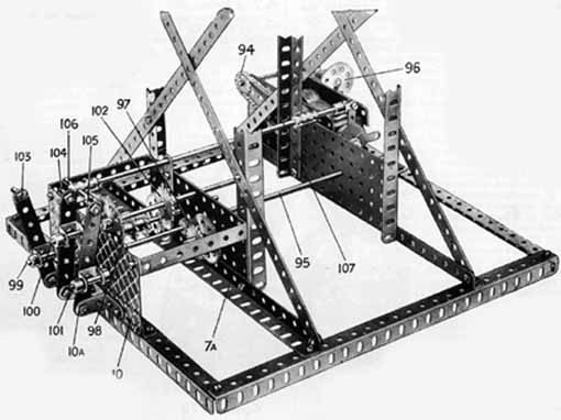
Fig. 9 Base
of Ship Coaler
List of Parts
Required for Building the High-Speed Ship Coaler
|
|
|
|
|
|
|
|