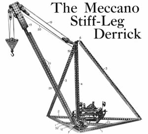
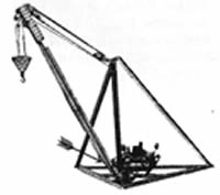
Special Features The Derrick is built exactly in accordance with real engineering practice. It is strong and very realistic in appearance. The load may be raised or lowered, or the jib luffed or swivelled, by manipulating convenient hand levers. |
Nº 6
With Radius Indicator . Fig.1 Greneral view of de model.The Radius Indicator is not included in the ilustraration, but its position is indicated in Fig.7.
|
Pag. 1
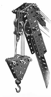 Fig.2Head of Jib, showing movable and fixed pulley blocks.
crane, it would perhaps be well to give some account of their functions, and the reasons for the particular method of construction that has been adopted. Apart from the base,
the derrick consists essentially of the following component parts :the jib,
the operating cables 19, the vertical member 4, and the two side members or ties 3.
These units combine to absorb all the strains and stresses generated in the crane while it is at work.
The jib, which is the most massive portion of the structure, is designed to receive as much as possible of the load imposed on the derrick.
Most of the strain on the jib head
is converted into compressive force applied to the jib itself,
the remainder being taken by the cables 19.
The jib is built up from two 24 1/2" Angle Girders 28 bolted together to form a T-girder. and strengthened by pairs of 12 1/2" and 7 1/2" Angle Girders bolted together and secured along the upper sides of the Girders 28. The head of the jib (Fig. 2) consists of two 5 1/2" Flat Girders secured to 2 1/2' Angle Girders
bolted in the first and fourth holes of the Girders 28.
A pair of 2" Strips bolted to the outer ends of the 5 1/2" Flat Girders provide bearings for two 2" Rods, to which are pivoted the pulley blocks of the jib head. The outer block, which forms part of the hoisting mechanism, consists of two 2 ½” Strips and one 3" Strip, in which are journalled 1" Rods.
Two 1" loose Pulley Wheels are mounted on one of these Rods, and the Strips are spaced as required by Washers and Collars. The inner or rear pulley block of the jib is built up of two 2 1/2" Strips and two 31/2".
Strips, and contains three 1" loose Pulley Wheels
mounted on a 1 1/2" Rod. Two 2 1/2" Triangular Plates, joined by 1" Axle Rods and spaced apart by Washers,
form the framework of the three-
sheave pulley block to which the Loaded Hook
is attached. Three 1" loose Pulley Wheels
free to revolve on one of the 1"
Rods,
and are separated by 2 1/2" Strips.
In each case the Pulley Wheels are spaced by Washers so that they may rotate quite freely.
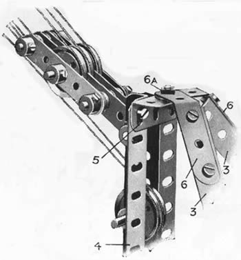 Fig.3Top of vertical member, showing method of attaching the tie members.
Vertical Member, Ties, etc.
The tension on the cables 19 is transmitted by the latter to the upper end of the vertical member 4, where the major portion of the strain is borne by the tension members 3. The cables 19 and ties 3 are pulling against each other
in directions corresponding to their respective positions, and as the two forces are not in direct opposition they combine in producing a force that tends to depress the upper ends of the tie members 3. This force takes the form of a downward thrust on the vertical member 4.
Therefore the latter,like the jib, must be designed
to withstand compression. Accordingly it is constructed from a pair of 18 1/2" Angle Girders
bolted together at each extremity, as well as at a point near the lower end, by 11" Angle Girders 5 (see Figs. 3 and 4).
The lowest of these 1 1/2" Girders is secured to a 3" Sprocket Wheel 7, which forms the swivelling base of the jib. The pivot is a 1 ½” Rod, which is passed through the centre hole of the lowest 1 1/2" Angle Girder 5 and through the boss of the Sprocket Wheel, and is carried in
a bearing 8 built up fromtwo 2 1/2" Strips bolted across the base Girders 1. Two Collars should be placed on this Rod, one above the Sprocket Wheel 7 and one below the 2 1/2" Strips 8 (Fig. 4).
A Corner Bracket 11 is bolted to one of the 1 ½” Angle Girders 5, as shown in Fig. 4, and two vertical 2 1/2" Rods 10 are journalled in the Bracket and in the 3" Sprocket Wheel. Two Flanged Wheels butted together and secured to each of the Rods 10 form guide pulleys 9 (Fig. 4). Two 1" loose Pulley Wheels 32 (Fig. 1),
which also act as guide Pulleys, are mounted
on horizontal Axle Rods journalled in the Girders of the vertical member 4.
A 2 1/2" Rod, about which the jib pivots in a vertical plane, is journalled through Trunnions 12 secured to the member 4 (Figs. 1 and 4) and through the end holes of 2" Angle Girders bolted in the first and third holes of the 24 1/2" Angle Girders 28 of the jib.
The side members 3 are required to withstand tension only and may be of comparatively light construction, for there is no need for them to be rigid, and steel has a very high tensile strength. They are made of single 24 1/2" Angle Girders, extended at their lower ends by 2 ½” Girders overlapped three holes. The 2 2/2” Strips 6 (Fig. 3), bolted to the tops of the Girders 3, are bent slightly as shown, and together form a bearing for the bolt 6a.
The latter is secured to the Strips by two nuts (see Standard Mechanism No. 262) and its shank forms a pivot about which turns the upper end of the vertical member 4.
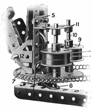 Fig.4Swivelling base of jib.
Pag.2
The Gear Box
Electric Motor, which The Meccano supplies the power for operating the Derrick, may be of either the 4-volt or the high-voltage type. It is bolted to a 5 1/2" Flat Plate supported on two 12 1/2" Angle Girders 15, and owing to its position
outside the triangular base it helps to counterbalance the weight of the jib and its load.
Three 61" Axle Rods 18, 21 and 33, and two 8 1/2" Rods 16 and 25 are journalled through the 5 1/2" by 2 1/2" Flanged Plates that form the sides of the gear box. The 6 1/2" Rods are retained in position by Collars, 34 but the 8" Rods are slidable in their bearings. The power from the
Motor is led through two 3 : 1 reduction gears,each consisting of a y Pinion Wheel and a 57-teeth Gear Wheel, and then is transmitted via a f *
Sprocket Wheel and a length of Sprocket Chain 17 to a 2" Sprocket Wheel on the Rod 16. A second 2" Sprocket Wheel on this Rod is connected with a 1* Sprocket Wheel on the Rod 25.
The lower end of the Strip 26. which serves as a hand lever and is pivoted to a Trunnion on one of the transverse 5 1/2" Strips of the gear box, engages two Collars secured to the Rod 25. By moving the lever 26 to the right, a 1/2" Pinion on the Rod 25 is caused to mesh with the 57-teeth 30 Gear Wheel 22, and thus the power
is communicated to the Rod 33.AWorm on this Rod operates a further 57-teeth Gear Wheel on the vertical Rod 27, which, in its turn, carries a 1" Sprocket Wheel that swivels the jib by means of a Sprocket Chain passing round the 3" Sprocket Wheel 7.
Luffing and Hoisting Movements
The luffing movement of the jib is brought into operation by moving the Crank 24. The Crank is connected by a 5" Rod to the Coupling 30, which, by means of a 1" Rod in its end transverse
hole engaging two Collars on the Rod 16, causes the latter to slide in its bearings.
When the Rod 16 is moved as far to the right as possible, the 1" Gear Wheel 31 engages a similar Wheel on the Rod 18, and the latter winds or unwinds the cord 19 according to the direction in which the Motor is running. This cord 19 passes between the guide pulleys 9 at the base of the upright
member 4, round one of the Pulley Wheels 32, and over a similar Pulley Wheel near the top of the member 4. It is then led in turn round each of the sheaves in the pulley blocks on the jib and the vertical member,
and is tied finally to the tail of the block on the jib.
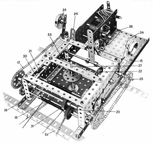 Fig.5 Plan view of Gear Box,showing High-voltage Motor in position for driving the model.
 By the use of this arrangement of pulleys a considerable mechanical advantage is obtained, which enables the jib to be luffed by the application of a very small force, even when the load Hook is carrying a considerable weight.
When the Rod 16 is in its central position
it revolves idly, but when, by means of the
Crank 24, it is moved over to the left the 1"
Pinion Wheel 23 meshes with a 57-teeth Gear
Wheel on the Rod 21, which operates the
hoisting-block by means of the cord 20. The
latter is conducted between
the guide pulleys 9, round
the lower and upper Pulleys
32, and over a l 1/2" Pulley
Wheel in the jib head.
Next it passes in turn
around each of the Pulley
Wheels in the hoisting-
block and in the outer
pulley block of the jib, and
finally is tied as shown to the tail of the upper block From the above it will
be clear that the lever 26 controls
the swivelling movement of the crane while the handle 24
controls
the raising and lowering of
the load on the Hook and
the luffing of the jib.
Reversing is effected, of
course, by means of the
starting handle of the Electric Motor.
Two brakes, consisting of weighted Strips 34 connected to cords engaging the grooves of 1" fast Pulley Wheels on the Rods 18, 21, prevent the cords 19, 20 from unwinding when their respective gears are disengaged and thus obviate any danger of falling-back on the part of the jib or hoisting-block.
Determining the Strength of a Crane.
Most Meccano boys probably know that the load capacity of a crane varies according to the particular angle of the jib, for the nearer the latter approaches the horizontal
position the greater will be the strains upon it in proportion to the load. This statement may be verified quite easily by applying the well-known principle of the Triangle of Forces,
which may be summarised as follows :
Pag.3
If three forces meet at a point and are in equilibrium, and we know one of the forces, we may determine the other two by drawing a triangle, making each side parallel to the direction of one of the forces,
and comparing the dimensions of the three sides. It will be found that these dimensions are in the same proportion as the three forces.
For example, supposing the side corresponding to the known force is four units in length and the others are eight and ten units, and supposing the known force is four tons, then we know that the other two forces must equal eight and
ten tons respectively.
In the case of a crane the three forces are
(a) the load suspended from the head of the jib,
(b) the tension member, or tie, which supports the jib (in luffing cranes the operating cable or chains, etc., with which the jib is raised or lowered correspond to the tie members),
and
(c) the jib, which acts as a strut to withstand the compressive force, exerted by the combination of (a) and (b). All three forces meet in the head of the jib and counterbalance each other : that is to say, they are in equilibrium.
By drawing one or two triangles and showing the side that is parallel to the jib in a different position in each triangle, it will be found that the strains that the crane structure must withstand increase as the jib approaches more nearly the horizontal position, as stated above. It should be noted that
the disposition and proportion of the strains or forces vary according to the particular type of crane.
Functions of a Radius Indicator
These facts render it impossible for an engineer to build a luffing crane
that will lift a specified load with equal facility at any position of the jib. He therefore designs his crane to lift a certain load at a certain radius, the radius being measured from the point about which the crane pivots to a point immediately beneath the load hook. Thus a swivelling and luffing crane that is
described in the specification as capable of raising with safety a load of 20 tons at a radius of 20 feet may be able to lift only 10 tons or thereabouts at a radius of 35 feet.
Therefore, when lifting a heavy load with a crane of this type, care must be taken to see that the jib is at the proper angle to cope with that load. A margin of safety is allowed, of course, for each of the various positions of the jib, but if this margin is overstepped, excessive strains may be
set up in the structure and machinery.
It is to minimise the possibility of such a mistake
being made that a radius indicator is fitted to the majority of luffing cranes.
A glance at this indicator tells the operator the position of the jib and the maximum load that he can handle safely without increasing the angle of the jib. Hence the device not only saves time but also obviates a considerable risk of accidents.
Construction of the Meccano Radius Indicator
Fig. 6 shows the indicator attached to the side of the jib in the Derrick, and the actual position of the device in relation to the remainder of the model is indicated more clearly by the arrow in Fig. 7.
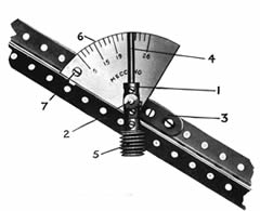 |
Fig.6 The meccano Radius Indicators attached to de jib of Derrick
|
The Coupling 1 is free to turn about the li" Axle Rod 2, which is gripped in the boss of a Crank 3 bolted to the upturned flanges of the jib girders. It carries in its upper end a further 1 1/2 " Rod 4 and in its lower end a 1" Rod on which is secured the Worm 5. The weight of the latter serves to keep the Rod 4 always vertical, no matter in what position the jib is placed. A dial 6, shaped from a piece of stout cardboard, is bolted at 7 to an Angle Bracket attached to the jib. The Rod 2 passes through a hole in the dial and carries two or three Washers to space the Coupling 1 away from the card so that the Worm 4 will clear the edges of the girders forming the jib. The jib should now be placed in different positions and the radius covered by the load hook for each position should be marked on the card.
An indicator of this type proves very useful when loading, say, a stationary lorry or railway wagon, for the jib-angle required to bring the load directly over the vehicle having once been noted, each succeeding load can be swung round and luffed immediately to the correct position. In addition, interesting experiments may be made by means of the indicator and the load capacity and efficiency of various types of Meccano Cranes tested.
Parts required for building the Stiff-Leg Derrick
2 of No. 12 |
2 of No. 26 |
50 of No. 59 |
|||
2 |
13a |
3 |
27a |
1 |
62 |
4 |
14 |
2 |
31 |
1 |
63 |
1 |
16 |
1 |
32 |
2 |
76 |
3 |
16a |
3 |
35 |
1 |
94 |
4 |
17 |
79 |
37 |
2 |
95a |
9 |
18a |
88 |
38 |
1 |
95b |
5 |
18b |
2 |
40 |
2 |
96 |
6 |
20 |
1 |
48b |
2 |
103 |
] |
21 |
2 |
52 |
3 |
126 |
2 |
22 |
2 |
52a |
1 |
133 |
15 |
22a |
1 |
57b |
1 Electric Motor |
|
| 2 of No. | 2 |
| 6 " " | 3 |
| 2 " " | 4 |
| 12" " | 5 |
| 2 " " | 6 |
| 5 " " | 7 |
| 4 " " | 7a |
| 5 " " | 8 |
| 2 " " | 8b |
| 6 " " | 9b |
| 2 " " | 9e |
| 3 " " | 9f |