(No.
1)
New
Meccano Motor Chassis
Special Features:
Three-speed forward and Reverse
Gear Box, Differential Gear, Ackermann Steering,
Friction Clutch, Torque Rods, Internal-expanding Brakes, Foot Brake on
Cardan Shaft,
Radiator Fan, Semi-elliptic Laminated Springs, Disc Wheels, Dunlop Tyres,
etc.
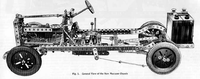
THE Meccano Motor Chassis forms not only an excellent example
of the adaptability of the Meccano parts but also a striking illustration
of the educational value of the Meccano system. It shows how, with the
aid of a number of ordinary Meccano parts, any intelligent boy may build
a complete working model that demonstrates the principles of modern motor
engineering so well that replicas of it have been used to instruct pupils
in numerous technical schools. The motor chassis about to be described
embodies numerous
improvements upon models of a similar type that have been published previously,
and it may be regarded as representing the latest Meccano practice. Amongst
the improvements may be mentioned the unit principle of construction that
has been adopted. The motor, clutch and gearbox are all mounted on a rigid
frame, which may be detached from the chassis merely by loosening two
or three screws. The differential and rear axle casing, with torque rods,
etc., also form a complete unit, the removal of which is the work of a
few seconds onlv.
Page1
The gearbox provides three speeds forward and reverse gear, and
is controlled by a central gear-change lever sliding in a quadrant that
retains it m position after each change is effected. The clutch is controlled
by a foot pedal and is fitted with a small Meccano Rubber Ring, the resilient
nature of which enables the drive from the motor to be taken up very smoothly
and gradually and transmitted to the road wheels. The differential gear
has been improved and made more compact. The back axle unit is mounted
on cantilever springs and any twisting tendency set up by the thrust of
the propeller shaft is counteracted by torque rods attached to the main
frame by a spring connection.
The steering gear is designed according to the Ackermann principle, which
provides for a different angle of turning movement in each front road
wheel. Internal expanding brakes are attached to the rear wheels and a
pedal-operated brake is fitted to the cardan shaft immediately in front
of the universal joint. Other refinements of the model include a radiator
cooling fan and a motor starting switch mounted on the dashboard.
The chassis will carry easily the weight of the Meccano 8 ampere-hour
Accumulator, even on top gear. The Accumulator should be placed on the
luggage carrier at the rear of the model, thus converting the chassis
into a self-contained power unit.
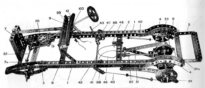
The construction of the model should be commenced by building the mam
frame, which is shown more clearly in Fig. 2. Each side consists of two
121/2" Angle Girders 1 bolted together in the form of a channel section
to give maximum rigidity. The side girders are held together by a cross
member 2 composed of a 51/2" Angle Girder and their front ends are
extended by 51/2" Curved Strips to carry the ends of the front semi-elliptic
springs. Each inner 51/2" Curved Strip is secured to the upper Girder
of its respective side member by means of two Angle Brackets. Two of the
bolts that serve to secure the Curved Strips also serve as pivots for
the shackles (Flat Brackets 3) supporting the rear ends of the front springs
(see also Figs. 4 and 6). The bolts should be secured to the side members
by two locked nuts (see Meccano Standard Mechanism No. 262) so that the
Flat Brackets are quite free to turn on their shanks.
The Frame and Springs
The main frame is extended and carried over the back axle by means of
a series of 2 1/2" large radius Curved Strips 4 bolted together in
the manner shown. The luggage carrier 5 is composed of two 3" Strips
connected by four 41" x 1/2" Double Angle Strips. The carrier
is bolted to the end holes in the main frame, and nuts on bolts 6 inserted
in the end holes of the 3" Strips strike against the Curved Strips
4 and thereby maintain the carrier in a horizontal position. The carrier
is designed to hold the Meccano 8 amp Accumulator, and when not in use
it may be folded back.
The radiator is represented by a 3 1/2"x 2 1/2" Flanged Plate
7 with two 3 1/2" x1/2" Double Angle Strips bolted at the sides.
It is secured to a 41" Strip 7a mounted between the front 5 1/2"
Curved Strips of the frame. The
Page 2
5 1/2 X 2 1|2"
Flat Plate 8 is secured to a 5 1/2" Angle Girder bolted to the main
side Girders 1 and is extended at the top by a 5 1|2" Strip 9 secured
at each end by Flat Brackets. The dashboard 10 consists of a 51|2"
Strip and a 5 1/2" Curved Strip attached to the Plate 8 by means
of two 1" Reversed Angle Brackets. The outer ends of these Brackets
should be bent slightly to obtain the correct angle for the dashboard.
The springing is a very important consideration in the construction of
any motor vehicle. The a rings must be so designed that they will stand
up to the strains imposed by heavy loads or violent locks and yet be so
sensitive that they will absorb lesser vibrations. Those included in the
Meccano Chassis are a faithful reproduction of the type used in the majority
of motor cars.
It will be seen from Fig. 6 that the front springs are of the semi-elliptic
type, and that each
consists of one 5 1/2", one 4 1/2", one 3 1|2", one 2 1/2",
and one 1 1/2" Strip placed one upon the other
and slightly bent. Each end of the 5 1|2" Strip is secured to a Double
Bracket. The rear
Double Bracket is bolted pivotally (S.M. 262) to the pair of-Flat Brackets
3, which form
shackles by means of which the rear ends of the springs are attached pivotally
the frame. The front Double Bracket is mounted on a 3/4" Bolt passing
through
side frame members (Fig. 4).
The rear springs are of the cantilever type, and one of them is shown
in let ail in Fig. 9. Each spring is built up from the same components
as the front
prints and is attached rigidly to the frame by two Angle Brackets (see
Fig. 2).
Principles of Ackermann Steering
It has already been mentioned that the steering gear is based on the Akermaun
principle but the importance of the different angularities of the from
wheels may be a point that has escaped the notice of many Meccano boys.
Perhaps it will not be out of place, therefore, to insert here a brief
summary of the principle of the gear.
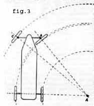
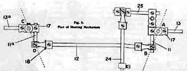
When a car turns a corner the near side road wheels describe curve sharper
than the outer wheels. This will be clear on reference to Fig. 3. the
drawing is intended to represent a car turning a corner, and in doing
.o it will be apparent that the wheels must describe an arc or portion
of a
circle whose centre is shown at A.
Now although both front wheels must turn about this centre they are situated
at varying distances from it. This means to say that
the right-hand front road wheel must follow an arc having a radius equal
to AB, and the left-hand wheel must follow an
arc struck from a larger radius AC. For the wheels to describe ' an arc
of a circle with the least , possible friction on the road surface, each
must be situated at a tangent to its respective circle. But it is obvious
that both wheels
cannot lie at their respective tan¬gents and at the same time remain
parallel to some method by means of which a the wheel that is nearest
to the centre of the circle, no matter whether the car be turning to right
or left. The arrangement by which this object is achieved constitutes
what is known as Ackermann steering gear. In actual practice, the gear
consists essentially of two short levers rigidly connected to the stub
axles and projecting either forward or backward. These levers lie at a
slightly obtuse angle to the stub axles. The correct angle is arrived at by fixing the levers so that their centre lines, if produced, would meet on the centre line of the car. The exact meeting place varies according to the size of the car and length of the levers, but as a rule it is found to be just in fronteach other.Hence it becomes necessary to incorporate in the steering gearAsome method by means of which a greater angle can be given to the wheel that is nearest to the centre of the circle, no matter whether the car be turning to right or left. The arrangement by which this object is achieved constitutes what is known as Ackermann steering gear. In actual practice, the gear consists essentially of two short levers rigidly connected to the stub axles and projecting either forward or backward. These levers lie at a slightly obtuse angle to the stub axles. The correct angle is arrived at by fixing the levers so that their centre lines, if produced, would meet on the centre line of the car. The exact meeting place varies according to the size of the car and length of the levers, but as a rule it is found to be just in front of the back axle. the levers are conneted one to the other by a tie rod.
Page3
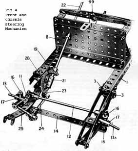
The Chassis Steering Gear
In Meccano practice it has been found a little difficult to secure the
necessary angles in the levers and at the same time maintain a perfectly
rigid construction, and therefore, a slightly different method has been
adopted. This comprises short Rods 11 and lla (Figs. 4 and 5) secured
just behind the stub axles and
protruding backward. They are connected together by a 5" Rod 12.
A plan view of this linkage is shown in Fig. 5, and it will be seen from
the drawing that imaginary lines AB, CD drawn through the pivotal mountings
of the stub axles and through the points where the tie rod 12 is attached
to the rods 11 and lla correspond roughly to the angles at which the levers
would be placed in actual practice.
Now if the car is to be turned to the right when looking at the gearing
as in Fig. 5, the road wheel on the stub axle 13 must be deflected in
that direction and the imaginary lever AB will be moved through a certain
number of degrees to the left. In doing so it pushes the lever corresponding
to CD in our sketch in the same direction, but owing to the difference
in angularity between the two levers, lever CD and therefore the road
wheel attached to its stub axle 13a, moves through a lesser number of
degrees. If the car moves to the left exactly the opposite occurs, the
lever CD moving through a greater number of degrees than the lever AB.
Therefore this arrangement of the linkage fulfils the essential requirements
of the Ackermann steering gear, that is, it imparts a greater angular
movement to the inner road wheel when the car turns a corner.
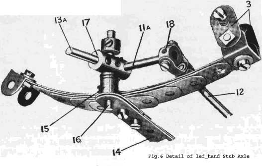
The mounting of the stub axle 13a is shown in detail in Fig. 6. The fixed
front axle 14 consists of two 5 1\2" Strips overlapped two holes
and supporting at each end a Crank 15. A 1 1/2" Axle Rod 16 secured
in each Crank 15 serves as a vertical swivel pin upon which a Coupling
17 carrying the stub axle (a 1" Axle Rod) is free to turn. The Coupling
17 in Fig. 6 carries the 1" Rod lla, to which is secured a Swivel
Bearing 18 (Part No. 165). The fork of the latter is fixed to the tie
rod 12, the other end of which is connected to the other stub axle by
another Swivel Bearing secured to the 1 1/2" Rod 11 (Figs. 4 and
5).
The connections between the steering wheel and the road wheels form another
important point that must be considered in connection with thesteering
gear. The gear ratio, or extent of movement of the road wheels to a given
movement of the steering wheel, must not be too high, otherwise a slight
twist of the wheel would result in a considerable deflection of the car,
which would be dangerous and might easily cause accidents. On the other
hand, if the ratio is too low the car would be slow to respond to the
wheel and therefore difficult to manage in dense traffic. In actual practice
the gear reduction is effected in various ways, principally by worm and
nut mechanism, but in the Meccano model the most convenient method was
found by gearing a 1|2" Bevel 19 with a 11|2" Bevel Wheel 20,
Fig. 4. The latter is free to turn on a 11|2" Rod journalled in the
side frame member and secured in the centre of a Coupling 21. One end
of this Coupling forms a journal bearing for the end of the steering column
22, which consists of an 8" Rod carrying a 2" Pulley Wheel to
represent the steering wheel.
A Flat Bracket 23 bolted to the 11\2" Bevel Wheel 20 forms the steering
lever, and a set-screw passed through its elongated hole is used to secure
a Collar to the 21|2" Rod 24. The other end of this Rod 24 carries
a Swivel Bearing, the collar of which is free to turn between two Collars
and set-screws on the 2" Rod 25. Nuts should be placed on the bolts
against the collar of the Swivel Bearing, to hold the bolts rigid without
gripping the Rod 25. The latter rod is fixed in a Coupling secured to
the 11|2" Rod 11. It will now be
seen that the movement of the steering wheel is transmitted to the right-hand
road wheel via the Bevel Wheel 20 and linkage 24 and 25, and the left-hand
wheel is caused to move simultaneously but at a different angle, as has
been explained already, by means of the Rods 11 and lla and tie rod 12.
The fixed front axle 14 is secured to the front chassis springs by means
of f" Bolts. The Cranks 15 should be bent so that the fixed swivel
pins 16 are slightly out of the vertical, with their upper ends pointing
out¬ward. This brings the points of contact between the front wheels
and the ground as nearly as possible beneath the centres of the swivel
pins. In actual practice the object of canting the swivel pins in this
way is to save the driver from fatigue and road shock, for if the centre
line of each road wheel was parallel with the centre line of the swivel
pin, all shock or vibra¬tions in the road wheel would act on the steering
wheel with a leverage equal to the distance that separates them. It is
specially important in cars fitted with four-wheel brakes, for the application
of such brakes on a car where
Page4
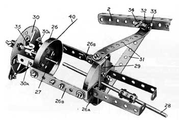 Fig7.
Back Axle Casing and Torque Rods
Fig7.
Back Axle Casing and Torque Rods
pin and wheel are parallel would tend to " toe out " the wheels.
Back Axle and Torque Rods
The back axle, which really consists of a fixed hollow casing, is repre¬sented
in the model by a framework of Strips, etc., that provides suitable bearings
for the two axle shafts and also forms a rigid connection between the
fixed portions of the rear wheel brakes (see Fig. 7).
The differential is housed in the back axle between two Wheel Flanges
26 and 26a, each of which is bolted against the inner side of a 2 1/2x1
1/2double AngleStrip. These Angle Strips are secured rigidly together
by means of 3" Strips 26b, and their centre holes form the inner
bearings for the axle shafts 27 and 28. In addition, shaft 28 passes through
the centre hole of a 21/2"x1/2Double Angle Strip 29 bolted to the
Wheel Flange 26a. One Washer should be placed between the Wheel Flange
and the Angle Strip 29 on each of the bolts that hold the latter in position.
The rear wheel brake mountings consist of two Face Plates 30 bolted rigidly
to the back axle casing, one being secured to the ends of two 1"
Reversed Angle Brackets and the other to the ends of two 2 1/2" x1/2|"
Double Angle Strips.
The rear axle casing (Fig. 7) performs several important functions in
addition to that of providing rigid bearings for the shafts secured to
the road wheels.
Besides carrying the weight of the vehicle, it must absorb the torque
or twisting reaction set up by the propeller shaft, and also transmit
the thrust of the road wheels to the chassis. The torque set up in the
back axle will be understood more clearly by studying the action of the
drive transmission between the propeller shaft and the road wheels. Suppose
that this is effected by a bevel pinion on the propeller shaft driving
a larger bevel gear secured to an unbroken axle carrying the two road
wheels : when the engine rotates, the small bevel pinion on the propeller
shaft will endeavour to rotate the bevel wheel on the back axle but since
this naturally is somewhat difficult to move, the pinion will tend to
travel round the bevel wheel while the latter remains stationary. This
state of affairs possibly might result in a snapped propeller shaft and
even broken springs, owing to the twisting movement imparted to the axle
casing.
It is to counteract these stresses and strains that motor vehicles are
fitted with what are known as torque rods. Many car manufacturers obtain
the required results by enclosing the propeller shaft in a torque tube,
which not only forms a torque reaction resistance, but also receives the
forward thrust of the back axle. In the Meccano model the torque rods
are shown quite separately from the propeller shaft, so that their functions
may be understood more readily.
The torque rods consist of two 51|2" Strips 31 secured to the ends
of the 2 1|2"x 1/2Double Angle Strip 29. These 51/2Strips taper together
at their other ends, where they are secured to a Collar 32 by means of
an ordinary bolt inserted in place of the grub screw. Two Washers should
be placed beneath the head of this bolt to prevent its shank from binding
on the 1/2Bolt 33, about which the Collar is free to pivot. The latter
bolt, in turn, is inserted in another Collar 34 that is capable of turning
about a Pivot Bolt secured to the 51/2Girder 2, which forms the main cross
member of the frame (see Fig. 2). A Compression Spring (part No. 120b)
is placed between the Collar and the Girder to act as a shock absorber
when the back axle is forced up and down by irregularities in the road
surface.
It will now be seen that the torque rods 31 effectively counteract any
twisting tendency in the back axle without interfering with the free vertical
movement of the latter as a whole or the independent movement of one or
other of the rear wheels.The
back axle casing is secured to the rear cantilever springs by an Angle
Bracket 35 secured to each Face Plate 30. These Angle Brackets are bolted
to the end holes of the springs, as will be seen in Fig. 2.
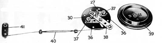 Fig.8.
Internal -expanding Rear Wheel Brake, ready for assembly
Fig.8.
Internal -expanding Rear Wheel Brake, ready for assembly
Page5
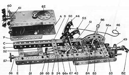 Fig.10General
View of Power Unit with Motor
Fig.10General
View of Power Unit with Motor
Brake Mechanism
One of the rear wheel brakes is shown in detail in Fig. 8, and it will
be seen that it is of the internal expanding type. Two 1/2" Bolts
are passed through opposite slots in the Face Plate 30 and their ends,
after passing through 1 1/2" Strips 36, are secured in Collars 37,
which form the brake shoes. Each 1/2" Bolt carries a Washer under
its head and two on its shank between the Face Plate and the 11/2"
Strips, 36. The latter Strips are pivoted by means of bolts and lock nnts
to a 21/2" Strip 38 that is free to turn about the axle shaft 27.
When the 2J" Strip is moved, the Collars are thrust outward along
the slots by means of the links 36 and pressed against the inside periphery
of a Wheel Flange 39 bolted to the inside of the road wheel. Three Washers
shoufd be placed on the axle 27 between the Strip 38 and the Face Plate.
Care should be taken to see that the \" Bolts are able to move quite
freely to and fro in the slots of the Face Plate.
The grub screws in the Collars 37 have been replaced by 7/32" Meccano
Bolts, and these are used to secure a short length of Spring Cord. The
latter serves to withdraw the brake shoes 37 and return the brake to the
" off " position when the Strip 38 is released. The road wheel
should be placed on the axle 27 with the Wheel Flange 39 towards the Collars
37. care being taken to see that the latter have plenty of room to move
before the road wheel is secured rigidly to the axle.
Fach brake rod 40 (see Figs. 2 and 8] consists of two Meccano loom Healds
bolted together (a length of cord will serve almost as well in their place
if preferred). The Healds are connected pivotally at one end to the Strip
38 by means of a bolt and two nuts (see S.M. 262) and at the other end
by a similar method to a Crank 41 secured to a 6 1/2" Rod 42 (Fig.
2). This Rod 42 carries a hand lever 43 (a 2 1/2" Rod) by means of
which the brakes are operated.
A second brake is fitted to the chassis and is operated by the foot pedal
44, the mounting ol which is clearly shown in the general view of the
power unit (Fig. 10). It will be seen that the lever consists of a 2 1/2"
large radius Curved Strip pivoted by its centre hole to a 'A3 1/2"
Rod 45 journalled in two Trunnions. A length of cord 46 (Figs. 2 and 10)
is tied to the second hole of the lever and is led under the 1/2"
loose Pulley 47 (Fig. 2), round a second 1/2'' Pulley 48 (mounted on a
Pivot Bolt secured in the end of a Single Bent Strip bolted to the cross
member '2') and thence round the groove of a 1" Pulley 49 (Fig. 10)
secured to the cardan shaft. The cord is finally brought back and tied
under the head of the Pivot Bolt carrying the Pulley 48. A slight pressure
on the pedal 44 tightens the cord round the Pulley 49 and thereby retards
the motion of the cardan shaft. When the brake is off the lower portion
of the pedal rests against a 3/4" Bolt 50 secured in one of the Trunnions,
and the pedal is held thereby in a convenient upright position.
The Power Unit
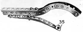 Fig.9
Detail of Cantilever Spring
Fig.9
Detail of Cantilever Spring
The 4-volt Electric
Motor representing the engine, and the gearbox, clutch, etc., are all
rigidly connected together, so that they form a complete unit that may
be removed from the chassis simply and quickly. This method of construction
ensures that the gear wheels and other working parts will always be in
proper alignment with each other, and that their functions will not be
affected in any way by stresses and strains set up in the chassis frame.
The main frame of the unit consists of two 91/2" Angle Girders 51
connected together by two 21/2" x 1/2" Double Angle Strips 52
and a 41/2" Strip 53. The Motor is secured to the frame by a bolt
passing through hole A in its side and hole B in the 31/2" Strip
54, and by two other bolts engaging the holes C and D of one of the 9J"
Girders. A Washer is placed on each of these bolts between the Motor and
the frame. It will be observed that the Motor rests on the far side 91/2"
Angle Girder (Fig. 10) onlv, and is bolted thereto. The near 91/2* Angle
Girder is not attached to the Motor except by the 3" Strip 54.
A 21/2" x 1/2" Double Angle Strip bolted across the two Double
Angle Strips 52 forms a bearing for the 5" Rod 56, which corresponds
to the crankshaft of an actual car. This Rod 56 carries a 1" fast
Pulley 57, a 1 1/2" Contrate Wheel 58, and a 1/2" fast Pulley
59 (Fig. 11). A length of cord connects the Pulley 57 with the 1/2"
fast Pulley 60 (Fig. 10) secured to the shaft of the radiator cooling
fan, which is free to rotate in the boss of a Crank 61. The latter is
bolted by its end hole to an Angle Bracket secured to the top of the Motor.
When the engine is in motion the fan rotates at a considerable speed immediately
behind the radiator.
Transmission—The Clutch
The drive from the Motor armature is first led to a secondary shaft 62,
on the lower end of which is secured a 1/2" Pinion, boss downward,
engaging with the 1 1/2" Contrate Wheel 58. The 1" Pulley 59
on'the 5" Rod 56 forms the male nortion of the clutch (Fiu. 11) and
's fitted with n Meccano Rubber Ring (Part No. 155), which provides the
resilient surface required in a frictional contact clutch of this type.
The female clutch member consists of a Flanged Wheel 63, with set-screw
removed, placed on the end of a 3V Rod 64.
The Flanged WTieel must slide on the Rod 64 and yet be mounted in such
a way that when it is engaged by the clutch member 59 it transmits power
to the Rod 64. This is accomplished in the following manner : two Angle
Brackets bolted to the Flanged Wheel by f" Bolts and spaced therefrom
by Collars engage by their slotted holes with the shanks of two set screws
inserted in the " spider " or central collar 65 of a Universal
Page 6
Coupling.
This " spider " is secured to the Rod 64 and a portion of a
Compression Spring 35a (part No. 120b) is inserted between it and the
boss of the Flanged Wheel. For this 65a'(part No. 120b) purpose it will
be necessary to cut the spring approximately in half. The Spring 65a
normally holds the Flanged Wheel in engagement with the Rubber Ring on
the Pulley 59,
but the Flanged Wheel can be forced back on the Rod 64 to an extent just
sufficient to
throw it out of gear with the clutch member 59.
The clutch withdrawal mechanism consists of a "2" Slotted Strip
66 (Fig. 10) bolted to a 11" Strip, the latter in turn being bolted
to a 1" x 1/2" Angle Bracket 67 that is connected by a bolt
and lock-nuts to the second hole of the pedal 55. The slot of the Strip
66 engages the Rod 62 immediately behind the Pinion driving the Contrate
Wheel 58. The Rod 62 thus forms a guide for the Strip 66, which moves
in a direction parallel to the Rod 56. It will be found that when the
pedal 55 is depressed the shank of the bolt 66a engages with the rim of
the Flanged Wheel 63, and the latter is thereby withdrawn from contact
with the clutch member 59.
Gear Box
The gear box provides three speeds forward, neutral, and reverse gears.
It is built up from two 41/2" Strips connected together at the front
end by a 21/2" x 1/2" Double Angle Strip and at the other end
by a 21/2" x 1/2" Double Angle Strip(Fig. 11). Tt is bolted
to the Angle Girders 51 in the position shown in Fig. 10 by means of four
Flat Brackets.
The 31/2" Rod 64 carrying the clutch member represents the primary
driving shaft. It is provided with a f " Pinion 68 and a 1"
Gear Wheel 69, and its inner end is journalled in the 1" x 1"
Angle Bracket 70. The countershaft consists of a 6 1/2" Rod 71 that
is slidable in the end Double Angle Strips of the gear box. This Rod carries
the following parts, reading from left to right in Fig. 11 ; two Collars
(acting as stops to limit its sliding move¬ment), a 50-teeth Gear
Wheel 72,1" Gear Wheel 73, two more Collars, one of which (74) is
free on the Rod, 3/4" Pinion 75, 1" Gear Wheel 76, and 1/2"
Pinion 77. These parts should be secured carefully in the positions indicated
in Fig. 11.
The driven 3" Rod 78 is journalled in the end Double Angle Strip
of the gear box and in a second l"x 1" Angle Bracket 70a. It
carries a 50-teeth Gear Wheel 79, 1" Gear Wheel 80, |" Pinion
81, the brake pulley 49, and the Universal Coupling 82. A Washer should
be placed between the 1/2" Pinion 81 and the Double Angle Strip.
This Pinion is in constant engagement with another 1/2" Pinion 83,
which is free to turn upon a £" Bolt secured to the end Double
Angle Strip by two nuts.
An ordinary 7/32" Bolt passes through the elongated hole of the Crank
84 and enters the threaded bore of the Collar 74. A nut placed upon it
is secured tightly against the Collar in order to prevent its shank touching
the rod 71 and also to ensure that the Crank is quite free to pivot about
the bolt. The Crank is secured to a 2" Axle Rod 85 (Fig. 10) journalled
in Angle Brackets bolted to the Angle Girders 51 of the power unit, and
a Coupling secured to this Rod carries the gear change lever 86.
It will be seen that the lever moves in a quadrant constructed from two
21/2" small radius Curved Strips bolted one on each side of l"x
1" Angle Brackets secured to the top of the power unit. The Curved
Strips are spaced away from each other by the thickness of the supporting
Angle Bracket and one Washer placed on each connecting bolt. In this way
the Curved Strips are caused to apply a certain pressure to the lever
86, which pressure is sufficient to hold the lever firmly in position
after each change of gear is effected.
The different speeds are obtained as follows. Assume that the sliding
rod 71 is at the furthest limit of its travel to the left in Fig. 11.
Then the drive from the engine is led thiough the following gears : 68,
72, 77, 83, and 81. The power is transmitted to the road wheels from the
Rod 78 by means of the Universal Coupling 82 and the propeller shaft.
When the mechanism is so placed the chassis runs backward, and the speed
ratio between the propeller shaft and the driving rod 64 is 1 in 2.
A slight movement of the gear change lever disengages the Pinion 77 from
Pinion 83, and " neutral " gear results, the secondary shaft
revolving idly without engaging any of the wheels 79, 80 or 83. Further
movement of the lever slides the Rod 71 further to the right and causes
the following gears to be engaged : 68, 72, 75, and 79. This gives first
speed forward, the ratio between shafts 78 and 64 being 1 in 4. Continuing
the movement of the lever, the second forward speed is obtained, the drive
now being directed as follows : 69, 73, 75, and 79. Ratio : 1 in 2.
When the lever is hard over and the rod 71 at the limit of its travel
to the right, the gears in engagement are 69, 73, 76, and 80. This represents
top forward speed, with a ratio of 1 in 1. Owing to the high speed of
the Electric Motor, the total ratio of speed reduction between the motor
armature and the back road wheels is fairly considerable. In reverse gear
the total gear reduction is approximately 1 in 48. In first forward gear
it is about 1 in 96, in second forward gear it is roughly 1 in 48, and
in " top " gear the road wheels rotate approximately once in
every 24 revolutions of the Motor.
The power unit is mounted in the chassis as follows. First remove the
radiator by unscrewing the Strip 7a (Fig. 2) on which it is mounted ;
remove the bolt 86a (Fig. 10) from the change gear lever quadrant, and
draw out the 5" Rod 87 (Fig. 2). Now place the power unit in position
and bolt the end holes of the 41/2" Strip 53 to the 1/2" Reversed
Angle Brackets 88 (Fig. 2), and replace the 5" Rod 87, passing it
through the holes E, F. G, of the Motor and power unit frame (Fig. 10).
Collars on the Rod 87 are next screwed tight against the power unit, and
the bolt 86a replaced in the gear lever quadrant. (This bolt was taken
out merely to obviate the necessity of removing the Rod 42, Fig. 2, which
passes through the centre of the quadrant). Replace the radiator and secure
the cord 46 of the foot brake in the position previously described.
Having secured the power unit in position, attention may be given to the
final stage in the transmission, i.e., the propelier shaft and differential.
Differential
Gear
In explaining the design of the steering gear it was pointed out that
when a car travels in a curved or circular path the two front road wheels
must each describe an arc struck from the centre of the circle or portion
of a circle in which the car moves, and the outer wheel must naturally
follow an arc of greater radius than the wheel that is nearer the centre
(see Fig. 3).
The difference in speed thus set up between the two wheels is not important
in the case of the front wheels, for they are both free to turn on their
individual axles ; but it is obvious that since the rear or driving wheels
are similarly placed in regard to the central point A, Fig. 3, the same
rule must apply to them. To state this more plainly, the rear wheels must
rotate at different speeds when the car moves in a curve, otherwise slip
must take place between the tyres and the road surface, which would result,
at least in the heavier types of car, in damage to the tyres and in more
or less severe inconvenience to the steering. But both these wheels must
be driven constantly from the engine and each must receive an
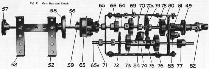
Fig.11. Gear _Box and Clutch
Page7
- equal
amount of driving power ; therefore it is necessary to incorporate in
the back axle some device th^t will transmit the power evenly to the
wheels and at the same time allow for the difference in speed that arises
mmediately the car deviates to any extent from the straight.
The mechanism that fulfils these functions is known as a " differential" or " balance" gear. In some cars, especially in heavy commercial vehicles, the differential is incorporated in a secondary shaft that is journalled in the main frame and connected at each end to one of the road wheels by means of chain or belt drive. The object of this is to reduce to a minimum the weight of the back axle, which is subjected to a continuous series of road shocks when in motion. In the Meccano model, the differential forms part of the back axle unit, and the principles of the mechanism should be clear from the following description.
The back axle shaft is in two sections, 27 and 28 (see Fig. 7). The former consists of a 3" Rod and the latter of a 4 1/2" Rod and a 2" Rod connected end to end by a Coupling as shown. The inner ends of the shafts 27 and 28 are journalled in opposite ends of a Coupling 89 (Fig. 12), in the centre transverse hole of which is secured a 2" Rod 93 that serves to carry the two 7/8" Bevel Gears 90 The set-screws of these Bevels should be removed so that they are free to turn about the 2" Rod. They engage with two similar Bevels 91 and 92 secured to the shafts 27 and 28 respectively.
The outer ends of the 2" Rod carrying the Bevels 90 are passed through the elongated holes of 1" x 1/2" Angle Brackets. The latter are secured rigidly by means of i" Bolts to opposite
holes in the 11/2" Bevel Gear 94, and are spaced therefrom by means of Collars placed upon the bolts between the Brackets and the Bevel Gear. This Bevel Gear is free to revolve independently about the axle shaft 28, its set-screw having been removed.
The propeller shaft consists of a 31/2" Rod 95, one end of which is secured in the Universal Joint 82 (Fig. 11) and the other end, after passing through a Double Bent Strip and the sid" of the differential frame, is secured in the1/2|" Bevel Gear 96, which engages with the \\" Bevel Gear 94. Two Collars 98 should be secured to the shaft 28 in the position shown to maintain the various gears in correct alignment and to prevent the gears 94 and 96 from slipping or binding against each other. A Washer should be placed between the outer Collar 98 and the Double Angle Strip forming the end of the differential frame, and two Washers should be placed against the boss of the 1/2" Bevel Gear 91.
Care should be taken to see that the various parts of the differential gear work quite freely and that the several Bevel Gears are all placed in the correct positions in relation to each other. Everything should operate smoothly and easily when the shafts 27 and 28 are twisted between thumb and finger, whether simultaneously and in the same direction, or separately and in opposite directions.
If one of the road wheels revolves at a greater speed than the other the Bevel Gears
90 begin to rotate and thereby adjust the difference in speed between the Bevel Gears
91 and 92. If the vehicle is running in a perfectly straight course the axles 27 and 28 and Bevel Gears 90, 91 and 92 must all rotate as one unit, since the road wheels are travelling at the same speed.
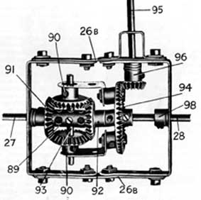 Fig.12
The New Differential Gear
Fig.12
The New Differential Gear
The construction of the differential frame will be obvious from Fig. 12. The two 2 1/2"x l 1/2" Double Angle Strips shown in this illustration may also be seen in Fig. 7, but in the latter case they are shown bolted to Wheel Flanges 26 and 26a and incorporated in the back axle casing. When the gear is ready to assemble, the differential frame (formed by the 21/2" x 1 1/2" Double Angle Strips and 3" Strips 26b) should first be incorporated in the fixed back axle (Fig. 7). The gearing should then be placed in the frame and the shafts 27 and 28 inserted in their respective positions. It will be noticed that a Washer is placed beneath the head of the bolts at each corner of the differential frame (Fig. 12) ; this is to prevent the shanks of the bolts fouling the sides of the Wheel Flanges 26 and 26a (Fig. 7).
Electrical Connections
All that now remains to complete the model is the wiring between the Motor, dashboard switch, and the Accumulator. Either the Meccano 8 amp. or 20 amp. Accumulator may be used, but the former is of a more convenient size. As previously pointed out, it may be mounted on the luggage carrier at the rear of the model.
One wire should be led direct from the Motor terminal to one terminal of the Accumulator, and another wire should be led from the second Motor terminal to a 6BA bolt 99 secured to the dashboard (see Figs. 2 and 4). This bolt is insulated from the 5 1/2" Curved Strip of the dashboard by means of a Meccano Insulating Bush and Washer. The switch handle consists of a Threaded Pin secured to a Flat Bracket 100, which is attached to the dashboard by another 6BA Bolt. An ordinary metal Washer should be placed on each side of the Flat Bracket, but the bolt is insulated from the dashboard by means of an Insulating Bush and Washer. A wire secured to its shank is led to the second terminal of the Accumulator. The Motor is started by sliding the Flat Bracket 100 over the head of the bolt 99, thus completing the electric circuit.
In connecting up the wiring care should be taken to see that the insulation is not damaged in any way, otherwise short circuits may be caused by the current leaking to the metal frame of the chassis.
It is scarcely necessary to add that all the working parts of the Chassis, with the single exception of the actual frictional surfaces of the clutch, should be lubricated at frequent intervals. Great care should be taken to prevent any oil coming in contact with the Rubber Ring on the clutch member 59 (Fig. 11), for the oil would cause the clutch to slip, of course, without transmitting the drive to the road wheels.
If the Meccano Chassis is to be used for demonstrating the actual working of a motor car, it will obviously be inconvenient to allow the model to run about or. its wheels. A good plan, therefore vs to jack up the model on suitable supports. A stand for this purpose can easily be devised by any boy from ordinary Meccano parts.
When the Chassis is raised in this way, with the wheels free to revolve, the various features of the mechanism may be studied while actually in motion and the different move¬ments, such as starting and stopping the Motor, clutching and declutching, gear-changing, reversing, and steering, etc., may be easily demonstrated.
/listadepaesList of Parts Required to Build the complete Motor Chassis
11 OF NO. 2 8 OF NO. 11 2 OF NO. 16A 9 „ „ 2A 24 „ „ 12 1 „ „ 16B 4 „ „ 3
4 „ „ 12A 5 „ „ 17 6 „ „ 4 4 „ „ 12B 5 ""18A 6 ""5 1 ""13 A 3"" 18B 9"" 6A 2"" 14 4 ""19B 4"" 8 2 ""15 1"" 20 2"" 9
1"" 15A 1"" 20A 12"" 10 5 ""16 3"" 22 -
2 OF Nº 232OFNº30C2 OF Nº 48B1 " "23A4""314""48C2""25178 ""371""534""2638 ""37A1""55A2""2740"" 383""581""27A1""4542""591""282""455""624""302""47A9""632""30A9""48A1""70
5OF Nº 891 OF Nº 1152OF Nº 147B14"" 902""120B1""1552""90A4""1241""1574""1012""1252 6BAScrews1"" 1022""1262 6BA Nut2"" 1091""1362 Insulating5""1114""137Bushes8""111A5""1402Insulating9""111C4""142Bwashers
Page.8
VOLVER A PLANOS