(No. 22)
Meccano Traction
Engine
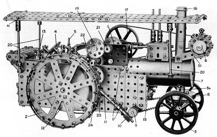
Fig.1General View of the Traction Engine |
THE
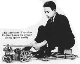
Meccano Traction Engine is not only a most realistic model, but it is
extremely powerful. The illustration at the foot of this page actually
shows the model pulling more than ten times its own weight! Any Meccano
boy of average weight should be able to build the model and then take
himself for a ride with it !
The Traction Engine was originally designed to be driven by a 4-volt Motor
supplied with current from a 4-volt 8 amp. hour Meccano Accumulator, and
in Fig. 1 the Accumulator is shown in the bunker at the rear of the model.
Since the Tractor was designed, however, the 4-volt Motor and 4-volt 8
amp. hour Accumulator have become obsolete, and have been replaced by
a 6-volt Motor and a 6-volt 20 amp. hour Accumulator.
The use of the new Motor does not involve any alteration in the construction
of the model itself, but the Accumulator cannot be placed in the bunker
on account of its larger size. It there¬fore must be carried on a
separate trailer hauled by the Tractor, or else placed on the ground and
connected to the model by a suitable length of twin flex.
|
Special Features The model is driven by a 6-volt Electric Motor supplied with current from a 6-volt 20 amp. hour Meccano Accumulator. The engine is capable of two speeds forward or reverse, and is fitted with worm and chain steering gear,external-contracting screw-operated brake, and imitation dynamo. The cylinder, crankshaft and reciprocating mec¬hanism of an actual steam engine are pro¬duced realistically in the model. |
Page1
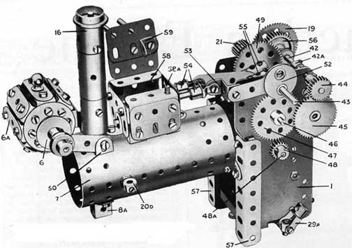
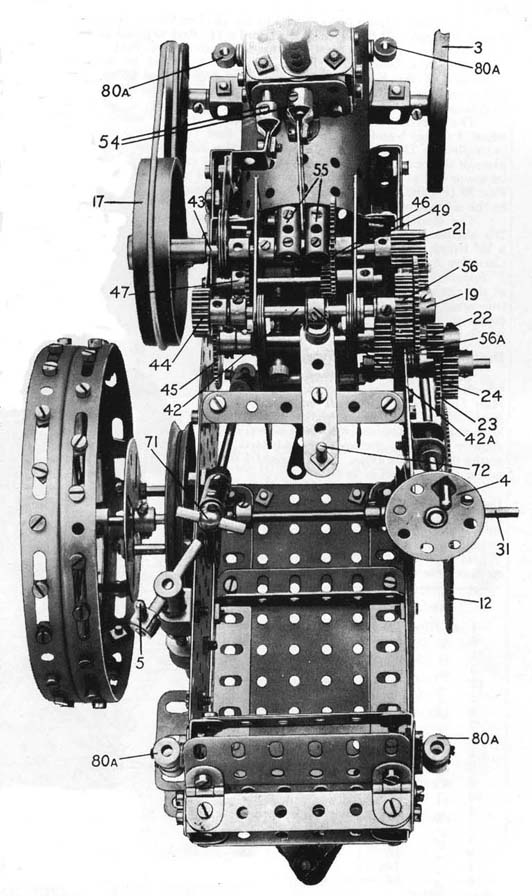
| Fig.2 View of the Boiler and Motor unit, showing cylinder block, dynamo, etc. |
The
trailer may be constructed on thelines
of the one illustrated on the front page. The base of this consists of
longitudinal 241/2" Angle Girders spaced apart by 121/2" Angle
Girders. A raised rear portion is constructed of further 121/2" Angle
Girders, and this may be used as a seat for the driver. The trailer is
mounted on four Wheels (Part No. 19a).
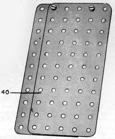
Main
Frame, Coal Bunker, etc.
The framework of the rear portion (Fig. 3) is constructed from two 51/2"X
31/2" Flat Plates 62 overlapped four holes and bolted together to
form each side of the main frame. The rear end is composed of two 21/2"x21/2"
Flat Plates overlapped four holes and bolted to Angle Girders secured
to the Flat Plates 62. Two 51/2" Angle Girders 64 are bolted to the
lower edges of the Plates 62 and are spanned by two 3" Angle Girders
39. Two 51/2"x 21/2" Flat Plates are secured to the Angle Girders
64 of the main frames.
Two 21/2"x 21/2" Flat Plates 63 bolted to the front ends of
the Plates 62 (Fig. 3) carry two2 1\2" Angle Girders to which are
bolted Corner Brackets 65 connected in the centre by the 1" Triangular
Plate 66 that carries an Angle Bracket 66a.
A 61/2" Rod 31 is journalled in the side Plates 62 and in 11 /2"
Pulley Wheels 37, which are secured to the inside faces of the Plates
to reinforce the bearings of the Rod. This Rod forms the axle for the
rear road wheels, and is held in position by Collars placed against the
bushes of the Pulley Wheels 37. The brake drum 30 is a 3" Pulley
Wrheel secured to the Rod 31, which also carries (on the opposite end)
a 31/2" Gear Wheel 12 placed so as to engage a 1" Gear Wheel
24. The latter is carried on a 2" Rod journalled in one side Plate
only of the frame and in another H" Pulley 38 bolted to the Plate.
This 2" Rod is held in position by a Collar secured against the bush
of the 1 " Pulley. It carries in addition to the Gear 24, a 57-teeth
Gear Wheel 23 that engages the 1/2" Pinion 22 (Fig. 1) of the Motor
unit. The Gear 23 (Fig. 3) is spaced from the frame Plate 62 by its boss
and several Washers, so as to give clearance for the steering column 11.
External-contracting Screw-operated Brake
A Threaded Pin 5 (Fig. 3) is secured in a Collar on a 101/2" Rod
and the latter is passed through the end of a Coupling in which is carried
a 3 1/2" Screwed Rod 5a journalled in two Double Brackets bolted
to the frame Plates as shown. The Screwed Rod carries a Threaded Boss
which, itis
important to note, must be free to move up and down on the Rod. The brake
cord is attached to a bolt on the frame, thence passed round the brake
drum 30 and secured to the Threaded Boss carried on the Screwed Rod 5a.
On turning the handle 5 the cord is tightened on the brake drum or slackened.
Boiler and Motor Unit
The
construction of tnis portion, which embodies the main gear train controlling
the travelling movements of the model, is shown in detail in Fig. 2. Two
31/2" Angle Girders 57 bolted to the flanges of the Electric Motor
form the supports by which the completed unit is secured later to the
rear portion of the model.
A Boiler 7 with front end plate is bolted to the Girders 57 and carries
on its upper surface the cylinder block 58, which is built up from six
11/2 " Flat Girders, eight 1/2"x 1/2" Angle Brackets, two
101/2" Angle Girders and two 11/2"x 1/2" Double Angle Strips.
The sides of the block are connected to the back and front cylinder covers
by Angle Brackets, whilst the top (consisting of two 11/2" Flat Girders)
is attached to the sides by means of the 11/2" Angle Girders. The
entire block is secured to the boiler top by means of two 11/2" Double
Angle Strips bolted to the bottom edges of the side Flat Girders, and
also by two Angle Brackets.
The
top of the cylinder block carries on the inside an Angle Bracket 59, in
the hole of which one of the 2" Rods 54 is jour nailed . This Rod
represents the piston rod and carries an End Bearing to which one end
of a 2" Strip is attached pivotally by means of a nut and bolt.
The other end of the 2" Strip is pivoted on the pin of the crankshalf
43.
|
Fig.3Main Frame, showing control handles and rear axle. Note de reiforcen bearings(37) for rear axle and the method of mounting the short Rod carrying the gear 23 and 24. |
Page.2
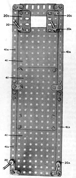
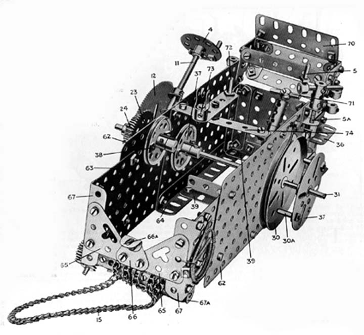
| Fig.4 The Canopy, undernearh view |
The
latter is built up as follows : Two Couplings 55 are secured at right
angles to two 2" Rods 43 (the Couplings should be fixed very securely
on their respective Rods by employing two Grub Screws in each Coupling)
and a 3/4 " Bolt is passed through their end holes to form the crank
pin. The crankshaft is journalled in the Motor side plates in the centre
of the top row of holes.
The valve rod is formed by the other 2" Rod 54 journalled in the
end cylinder cover and also in an Angle Bracket secured by means of a
bolt 58a to one of the 11/2" Angle Girders of the cylinder block
58. This Rod carries an End Bearing that is attached rigidly by nut and
bolt to a 1/2" Reversed Angle Bracket, which, in turn, is connected
pivotally by a bolt and two nuts (see Standard Mechanism No. 262) to a
Single-throw Eccentric 52 carried on the end of the crankshaft.
A "safety valve" composed of two Couplings carrying 11/2"
Rods (see Fig. 1) may now be mounted on the cylinder block as shown.
The chimney 16 (Fig. 2) is composed of three Sleeve Pieces placed end
to end with the ' centre Sleeve Piece overlapping each of the other two
by 3/8". A 31|2" Rod passed lengthwise through the centre of
the three Sleeve Pieces carries at one end a 3/4 " Flanged Wheel
that forms the top of the chimney. The top and bottom Sleeve Pieces are
held in place by means of bolts passed through them and inserted in the
holes of new-style Collars carried on the 31/2" Rod.
The dynamo is mounted on two 2" Strips secured to two Angle Brackets
50. of two Bush Wheels each carrying seven Angle Brackets to which are
secured A 21/2" Axle Rod passed through the two Bush Wheels carries
two 3/4 " Flanged Wheels 6, one wheel being placed on either side
of the dynamo. A y loose Pulley also is placed on one end of the Rod and
is spaced from the 3/4" Flanged Wheel by a Collar, while a further
Collar secured to the Rod on the outer side of the 1/2" Pulley holds
the latter in position ready to receive the belt from the Flywheel. The
dynamo lifting hook is formed by a Handrail Support fitted to one of the
1 1/2" Strips forming its frame.
When this stage of the construction has been reached, the Motor unit (Fig.
2) may be secured to the rear portion (Fig. 3) by bolts passed through
the Angle Girders 57 of the Motor unit and the end holes of the frame
plates 62 (Fig. 3) as shown at "D" in Fig. 1. The lower surface
of the Boiler is bolted to the Angle Bracket 66a (Fig. 3). The two units
are thus held securely in position.
The Main Gear Train
The main gear train is shown complete in Fig 5 but its principal com¬ponents
are illustrated more clearly in Fig. 2. The armature spindle of the Motor
(48a in the latter illustration) carries a 1/2" Pinion 48 that engages
with a 57-teeth Gear Wheel 47, on the Rod of which is also-carried a 1/2"
Pinion. The latter engages a 57-teeth Gear 49 on the crankshaft
The crankshaft also carries a 1/2" Double-width Pinion 21 that meshes
with a 57-teeth Gear Wheel 19 secured to a 31/2" Rod 42, on which
is also secured a 1" Gear Wheel 56. On the other end of the Rod 42
is a 3/4" Pinion 44. The Rod is slidable in its bearings and is controlled
by the lever 72 (Fig. 5). The latter is connected pivotally to a Small
Fork Piece (see Figs. 3 and 5) which engages a Collar 42a (Fig. 5) carried
on the Rod 42.
A 1" Gear Wheel 56a (Fig. 5) is secured to a 4 1/2" Rod journalled
in the Motor side plates, and a 1/2" Pinion 22 and a 50-teeth Gear
Wheel 45 are carried at either end of the same Rod. It will be seen from
Fig. 5 that by moving the lever 72 either of two gear trains may be brought
into operation, viz. :—the 1" Gear Wheel 56 may be brought
into engagement with the 1" Gear 56a, or the 3/4" Pinion 44
into engagement with the 50-teeth Gear 45 (in both cases the Gear 19 remains
in mesh with the Double-width Pinion 21). Hence the Motor drive may be
transmitted through two different gear ratios, resulting in a "fast"
and "slow" speed of the engine.
It will be noted that the Rod 42 and the Rod carrying Gears 45 and 56a
are mounted in reinforced bearings composed of 1 1/2" Strips bolted
to the Motor side plates.
When it is desired to run the engine without the tractor moving (such
as when driving the dynamo) the lever 72 should be placed in the central
position. In this position both the Gear Wheel 56 and the Pinion 44 are
disengaged from their respective gears and no power is transmitted to
the driving wheels. The reverse movement for either speed is obtained
of course simply by reversing the Motor.
Steering Mechanism
The front road wheels 3 (Fig. 6), which consist of 3" Wheels, are
carried on 1 1/2" Axle Rods 27 journalled in the holes of a 31/2"x
1/2" Double Angle Strip. The latter is secured to the inside of a
channel girder formed by two 31/2" Angle Girders 26 bolted together
as indicated. The inner ends of the Rods are journalled in
| Fig.5 Plan View, showing Crankshalft and Gearin. etc The slidingRod (42) and geachanging lever (72)are clearly shown. |
Page.3
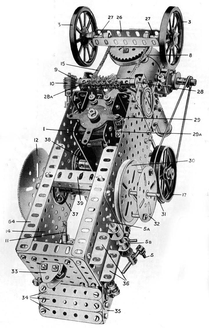
| Fig. 6 Underneath view,showing Steering Gear an Electric Motor, etc. The Brake on the rear axle is also clearly brought out in this view |
gle
Brackets bolted to the Girders and are held in position by Collars secured
to the Rods against the faces of the Angle Brackets.
The Wheel Flange 8 is secured to the Girders 26 by bolts passed through
a 2" Sprocket Wheel, and a 11/2" Rod secured in the latter acts
as a pivot for the front axle unit. The Rod is journalled in a Double
Bent Strip 8a (Fig. 2) bolted to the underside of the Boiler and in the
second hole of the Boiler, and is held loosely in position by means of
a Collar placed on the Rod inside the Boiler.
The steering mechanism is controlled from a steering wheel 4 (Figs. 1
and 3) secured to an 8" Rod 11 that is journalled in Double Brackets
bolted to the side frame plate of the rear portion. The steering Rod 11
carries at its lower end a Worm 10 engaging a 3/4" Pinion 9 on a
31/2" Rod 28 (Fig. 6), which is journalled in 11/2" Strips bolted
to the side plates of the framework.
The Rod 28 carries several Couplings and Collars 28a, the heads of the
grub screws of these serving to grip a 16" length of Sprocket Chain
that is wound round the Coupling five or six turns and thence passed round
the 2" Sprocket Wheel attached to the front axle. The ends of the
chain are of course joined together. By reason of this arrangement the
front wheels may be directed either to right or left according to the
direction in which the steering wheel is turned.
Building the Driving Wheels
The actual construction of the driving wheels should offer little difficulty.
Two Hub Discs bolted together and secured to a Bush Wheel (which acts
as a hub) form both the right and the left-hand wheel but slightly differing
methods are adopted to secure them to the axles. For the right-hand wheel
the method is as follows :Two 1/2" Bolts are secured by nuts to the
Hub Discs (Fig. 1). When the wheel is placed on the Axle Rod 31 (Fig.
5), it will be found that the shanks of the bolts will engage in the holes
or slots of the 3 1/2" Gear Wheel 12. The idea of this arrangement
is to provide a more secure hold for the road wheel
than would be possible simply by tightening the set-screws, of the Bush
Wheels secured to the Hub Discs.
In the case of the left-hand driving wheel it is necessary to space it
from the frame plate of the rear portion in order to allow sufficient
clearance for the Flywheel 17 (Fig. 5), and for this purpose a Face Plate
32 (Fig. 3) carrying two Threaded Pins is passed over the Rod 31 and its
set-screw tightened so that it is secured with the Threaded Pins engaging
slots or holes in the brake drum 30. The driving wheel may now be placed
in position, the 3/4" Bolts of the wheel engaging holes in the Face
Plate.
The Motor Control
The control handle for the 6-volt Electric Motor is shown at 71 (Fig.
5). By pulling or pushing this handle the Motor may be started, stopped,
or reversed. The handle, which con¬sists of a 1" Rod inserted
in a Handrail Support, is secured by a Coupling to a 41/2" Rod on
the lower end of which is a Swivel Bearing 29a (Fig. 6) attached pivotally
by a bolt 29 to one of the Motor switch arms.
A support and guide for the 41/2" Rod is formed by a Collar pivotally
attached by a bolt to the side plate of the frame, the bolt being locked
in position against the Collar by a nut (see Fig. 5). It is important
to note that the bolt does not nip the 4 1/2" Rod ; the latter must
be quite free so that the Motor switch may be moved by pushing or pulling
the handle 71.
The canopy (Fig. 4) may now be constructed. It is built up from three
51/2"x 31/2" Flat Plates 41 joined together with the centre
Plate overlapping the rear end Plate by three holes and the front end
Plate by four holes. The sides of the canopy are extended by 7 1/2"
Strips 41a joined to the Plates 41 by Flat Brackets, and the portion that
surrounds the chimney is formed by 2" Flat Girders 20c secured to
the front Plate 41 and to a 31/2" Flat Girder, the latter being joined
to the 71/2" Flat Strips 41a by Flat Brackets. The 31/2 Rods 20 forming
the supports for the canopy are secured in Couplings 20a, which in turn
are secured by bolts to the Plates 41. The lower ends of the Rods are
secured in Collars 8Oa carried on the Boiler and bunker frame Plates (see
Fig. 5).
To complete the model steps 36 (Fig. 6) consisting of 1 1/2" Angle
Girders should be bolted to the Plates of the main frame. Two Double Brackets
to which are bolted two 1" Triangular Plates form the coupling 33
by means of which the trailer draw-bar may be attached.
PARTS
REQUIRED
|
|
|
|
Page.4